Download
1 / 42
680 likes | 1.12k Views
Chapter 5 STP/RSTP/PVST+. Redundancy. Improves availability of the network. Issues with Redundancy. Layer 2 loops Ethernet frames do not have TTL Endless looping of broadcast frames Broadcast storms Unnecessary use of network resources Inconsistent MAC address tables

E N D
Chapter 5 STP/RSTP/PVST+
Redundancy • Improves availability of the network
Issues with Redundancy Layer 2 loops Ethernet frames do not have TTL Endless looping of broadcast frames Broadcast storms Unnecessary use of network resources Inconsistent MAC address tables Duplicate frames arriving at destination Wiring closet loops Two connections to the same switch Connections to switches that are interconnected Loops in cubicles Interconnected hubs/switches
Spanning Tree Protocol • Insures 1 logical path between all destinations • Blocks redundant paths • Maximum network diameter of 7
Spanning Tree Protocol Bridge Protocol Data Units (BPDU) are exchanged Contains Bridge ID (BID) Lowest BID is elected Root Bridge Lowest cost path to the root bridge is calculated Path cost Port cost All ports are assigned a role Root ports Designated ports Non-designated ports
Two Key Concepts: BID and Path Cost • STP executes an algorithm called Spanning Tree Algorithm (STA). • STA chooses a reference point, called a root bridge, and then determines the available paths to that reference point. • If more than two paths exists, STA picks the best path and blocks the rest • STP calculations make extensive use of two key concepts in creating a loop-free topology: • Determine Root through Bridge ID • Determine Best path to root through Path Cost
Bridge ID (BID) • BPDU sent every 2 seconds, Root ID is BID of root bridge • Bridge ID (BID) is used to identify each bridge/switch. • The BID is used in determining the center of the network, in respect to STP, known as the root bridge. • Consists of two components: • A 2-byte Bridge Priority: Cisco switch defaults to 32,768 or 0x8000. • A 6-byte MAC address
Bridge ID (BID) • Bridge Priority is usually expressed in decimalformat and the MAC address in the BID is usually expressed in hexadecimalformat. • BID is used to elect a root bridge • Lowest Bridge ID is the root. • If all devices have the same priority, the bridge with the lowest MAC address becomes the root bridge.
Path Cost • Shortest path is based on cumulative link costs. • Link costs are based on the speed of the link. • The Spanning-Tree Protocol establishes a root node, called the root bridge. • The Spanning-Tree Protocol constructs a topology that has one path for reaching every network node. • The resulting tree originates from the root bridge. • Redundant links that are not part of the shortest path tree are blocked. We will see how this works in a moment.
Four-Step STP Decision Sequence • When creating a loop-free topology, STP always uses the same four-step decision sequence: Four-Step decision Sequence Step 1 - Lowest BID Step 2 - Lowest Path Cost to Root Bridge Step 3 - Lowest Sender BID Step 4 - Lowest Port ID • Bridges use Configuration BPDUs during this four-step process.
Three Steps of Initial STP Convergence • The STP algorithm uses three simple steps to converge on a loop-free topology. • Switches go through three steps for their initial convergence: STP ConvergenceStep 1 Elect one Root BridgeStep 2 Elect Root PortsStep 3 Elect Designated Ports
Three Steps of Initial STP Convergence STP Convergence Step 1 Elect one Root Bridge Step 2 Elect Root Ports Step 3 Elect Designated Ports
Step 1 Elect one Root Bridge • When the network first starts, all bridges are announcing a chaotic mix of BPDUs. • All bridges immediately begin applying the four-step sequence decision process. • Switches need to elect a single Root Bridge. • Switch with the lowest BID wins! • Note: Many texts refer to the term “highest priority” which is the “lowest” BID value. • This is known as the “Root War.”
Step 1 Elect one Root Bridge Cat-A has the _________________, so it wins the Root War! All 3 switches have the same default ___________value of ___________
Three Steps of Initial STP Convergence STP Convergence Step 1 Elect one Root Bridge Step 2 Elect Root Ports Step 3 Elect Designated Ports
Step 2 Elect Root Ports • Now that the Root War has been won, switches move on to selecting Root Ports. • A bridge’s Root Port is the port closest to the Root Bridge. • Bridges use the cost to determine closeness. • Every non-Root Bridge will select one Root Port! • Specifically, bridges track the Root Path Cost, the cumulative cost of all links to the Root Bridge.
Step 2 Elect Root Ports Step 1 • Cat-A sends out BPDUs, containing a Root Path Cost of 0. • Cat-B receives these BPDUs and adds the Path Cost of Port 1/1 to the Root Path Cost contained in the BPDU. Step 2 • Cat-B adds Root Path Cost 0 PLUS its Port 1/1 cost of 19 = 19 BPDU Cost=0 BPDU Cost=0 BPDU Cost=0+19=19 BPDU Cost=0+19=19
Step 2 Elect Root Ports Step 3 • Cat-B uses this value of 19 internally and sends BPDUs with a Root Path Cost of 19 out Port 1/2. Step 4 • Cat-C receives the BPDU from Cat-B, and increased the Root Path Cost to 38 (19+19). (Same with Cat-C sending to Cat-B.) BPDU Cost=0 BPDU Cost=0 BPDU Cost=19 BPDU Cost=19 BPDU Cost=19 BPDU Cost=19 BPDU Cost=38 (19=19) BPDU Cost=38 (19=19)
Step 2 Elect Root Ports Step 5 • Cat-B calculates that it can reach the Root Bridge at a cost of 19 via Port 1/1 as opposed to a cost of 38 via Port 1/2. • Port 1/1 becomes the Root Port for Cat-B, the port closest to the Root Bridge. • Cat-C goes through a similar calculation. BPDU Cost=0 BPDU Cost=0 BPDU Cost=19 BPDU Cost=19 Root Port Root Port BPDU Cost=38 (19=19) BPDU Cost=38 (19=19)
Three Steps of Initial STP Convergence STP Convergence Step 1 Elect one Root Bridge Step 2 Elect Root Ports Step 3 Elect Designated Ports
Step 3 Elect Designated Ports • The loop prevention part of STP becomes evident during this step, electing designated ports. • Each segment in a bridged network has one Designated Port, chosen based on cumulative Root Path Cost to the Root Bridge. • The switch containing the Designated Port is referred to as the Designated Bridge for that segment. • To locate Designated Ports, lets take a look at each segment. • Root Path Cost, the cumulative cost of all links to the Root Bridge.
Root Path Cost = 0 Root Path Cost = 0 Step 3 Elect Designated Ports Segment 1 Segment 2 • Segment 1: Cat-A:1/1 has a Root Path Cost = 0 (after all it has the Root Bridge) and Cat-B:1/1 has a Root Path Cost = 19. • Segment 2: Cat-A:1/2 has a Root Path Cost = 0 (after all it has the Root Bridge) and Cat-C:1/1 has a Root Path Cost = 19. • Segment 3: Cat-B:1/2 has a Root Path Cost = 19 and Cat-C:1/2 has a Root Path Cost = 19. It’s a tie! Root Path Cost = 19 Root Port Root Path Cost = 19 Root Port Root Path Cost = 19 Root Path Cost = 19 Segment 3
Root Path Cost = 0 Root Path Cost = 0 Step 3 Elect Designated Ports Segment 1 Segment 2 Segment 1 • Because Cat-A:1/1 has the lower Root Path Cost it becomes the Designate Port for Segment 1. Segment 2 • Because Cat-A:1/2 has the lower Root Path Cost it becomes the Designate Port for Segment 2. Designated Port Designated Port Root Path Cost = 19 Root Path Cost = 19 Root Port Root Port Root Path Cost = 19 Root Path Cost = 19 Segment 3
Root Path Cost = 0 Root Path Cost = 0 Segment 1 Segment 2 Segment 3 • Both Cat-B and Cat-C have a Root Path Cost of 19, a tie! • When faced with a tie (or any other determination) STP always uses the four-step decision process: 1. Lowest Root BID; 2. Lowest Path Cost to Root Bridge; 3. Lowest Sender BID; 4. Lowest Port ID Designated Port Designated Port Root Path Cost = 19 Root Path Cost = 19 Root Port Root Port Root Path Cost = 19 Root Path Cost = 19 Segment 3
Root Path Cost = 0 Root Path Cost = 0 Segment 1 Segment 2 Segment 3 (continued) • 1) All three switches agree that Cat-A is the Root Bridge, so this is a tie. • 2) Root Path Cost for both is 19, also a tie. • 3) The sender’s BID is lower on Cat-B, than Cat-C, so Cat-B:1/2 becomes the Designated Port for Segment 3. • Cat-C:1/2 therefore becomes the non-Designated Port for Segment 3. Designated Port Designated Port Root Path Cost = 19 Root Path Cost = 19 Root Port Root Port 32,768.CC-CC-CC-CC-CC-CC 32,768.BB-BB-BB-BB-BB-BB Root Path Cost = 19 Root Path Cost = 19 Designated Port Segment 3 Non-Designated Port
Spanning Tree Operation - Summary • One root bridge per network • One root port per non root bridge • One designated port per segment • Unused, non-designated ports • Non-designated ports discard data traffic. These ports are called blocking (B) or discarding ports
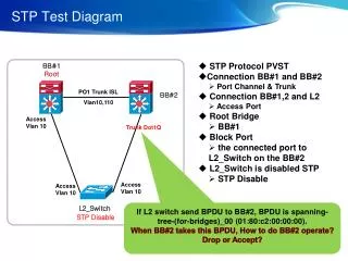
STP Exercise Determine the root bridge, root ports, designated ports and non-designated ports.
Changing Path and Port Cost • Path cost • Sum of port costs along path • Port cost • Defined by speed of port • Defaults set by IEEE • Configurable • S1(config-if)# spanning-tree costport_cost • port_cost range 1 to 200,000,000 • S1# show spanning-tree [detail]
Changing Bridge ID Priority Multiples of 4096 Range: 1 to 65536 Default: 32768 Configuration spanning-tree vlanvlan_idroot primary Sets priority to 24576 spanning-tree vlanvlan_idroot secondary Sets priority to 28672 spanning-tree vlanvlan_idprioritypriority_value Verification show spanning-tree
Port States Blocking Non-designated port Receives BPDUs Listening Sending and receiving BPDUs Learning Sending and receiving BPDUs Populating MAC table Forwarding Sending and receiving BPDUs Forwarding frames Disabled
Port Roles Root port Non-root switches Port with best path to root bridge Designated port Receives frames and forwards them toward the root bridge Non-designated port Blocked port Does not forward frames Does not populate the MAC table Disabled port Port is administratively down
BPDU Timers Hello time Time between BPDU frames Default: 2 seconds Range: 1 to 10 seconds Forward delay Time spent in listening and learning states Default: 15 seconds Range: 4 to 30 seconds Maximum age Length of time BPDU information is saved Default: 20 seconds Range: 6 to 40 seconds
Cisco PortFast • Port transitions from blocking to forwarding immediately • Use only on access ports • S1(config-if)# spanning-tree portfast
Topology Changes Topology change detected by a switch BPDU with Topology Change Notification bit set Sent out root port Receiving switch returns BPDU with Topology Change Acknowledgment bit set Sends TCN out it’s root port Root bridge broadcasts configuration BPDUs with Topology Change bit set
Rapid Spanning Tree Protocol (RSTP) IEEE 802.1w Most parameter left unchanged Different port States Much faster convergence than STP Link types Edge ports Ports never intended to connect to another switch Immediately transitions to forwarding state Point-to-point Immediately transitions to forwarding state Shared
RSTP Port States and Roles Port States Discarding Prevents forwarding of data frames Learning Populating MAC table Forwarding Data frames are being forwarded Port Roles Root port Designated port Alternate port Discarding
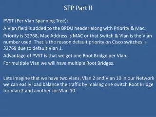
PVTS+ and Rapid-PVST+ Per-VLAN Spanning Tree plus (PVST+) Cisco proprietary Separate spanning tree for each VLAN Allows load balancing Rapid-PVST+ Cisco proprietary Cisco implementation of RSTP
Troubleshooting STP You must know Topology of the bridge network Location of the root bridge Location of the blocked ports and redundant links PortFast configuration error BPDU guard Disables port if BPDU is received Network diameter issues