Download
1 / 17
170 likes | 288 Views
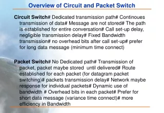
Circuit switch controller: Routing and signaling. Malathi Veeraraghavan University of Virginia. Circuit switch Routing Signaling Difference in use of addresses Examples used in practice. A network of circuit switches. Control plane Switch controllers exchange routing information

E N D
Circuit switch controller:Routing and signaling Malathi Veeraraghavan University of Virginia • Circuit switch • Routing • Signaling • Difference in use of addresses • Examples used in practice
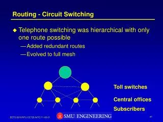
A network of circuit switches • Control plane • Switch controllers exchange routing information • Switch controllers exchange signaling messages to check if there is sufficient bandwidth to admit the call (call setup) and after use, release the bandwidth • Data plane • Data frames carrying user data are switched from link to link across each switch based on their "positions" (time slots/wavelengths)
Dest. Next hop III-B III-B III-C III-C Dest. Next hop III-* III Control plane: Routing protocol exchanges+ routing table precomputation • Similar to the routing protocol exchanges used in connectionless (CL) packet-switched networks • More emphasis on exchanging loading information II 4 5 1 Host I-A Host III-B I III 1 1 IV Host III-C Dest. Next hop III-* IV Routing table (will have other entries)
Control plane: Signaling Call setup Connection setup (Destination: III-B; Bandwidth: OC1; Timeslot: a, 1) Connection setup actions at each switch on the path: • Parse message to extract parameter values • Lookup routing table for next hop to reach destination • Read and update CAC (Connection Admission Control) table • Select timeslots on output port • Configure switch fabric: write entry into timeslot mapping table • Construct setup message to send to next hop II a b Host I-A a III b I Host III-B c b d c IV a Dest. Next hop Routing table III-* IV
Call setup contd. Connection setup (Destination: III-B; Bandwidth: OC1; Timeslot: a, 1) Connection setup actions at each switch on the path: • Parse message to extract parameter values • Lookup routing table for next hop to reach destination • Read and update CAC (Connection Admission Control) table • Select timeslots on output port • Configure switch fabric: write entry into timeslot mapping table • Construct setup message to send to next hop II b a Host I-A a b III I Connection setup Host III-B c b d c IV a Dest. Next hop Routing table III-* IV Interface (Port); Capacity; Avail timeslots CAC table Next hop c; OC3; 1, 3 IV INPUT Port /Timeslot OUTPUT Port/Timeslot Timeslot mapping table a/1 c/3 Update to remove timeslot 3 from available list
Call setup contd. II b a b Host I-A a Connection setup III I c Host III-B b d c IV a Connection setup (Destination: III-B; Bandwidth: OC1; Timeslot: a, 3) INPUT Port /Timeslot OUTPUT Port/Timeslot say, timeslot 2 was free on interface c a/3 c/2 Output time slot assigned for a given circuit at a switch is the same as the input time slot assigned to that circuit at the next-hop Perform same set of 6 connection setup steps at switch IV write timeslot mapping table entry, update CAC table and send connection setup message to the next hop
Call setup contd. INPUT Port /Timeslot OUTPUT Port/Timeslot II d/2 b/1 b a Host I-A a Connection setup III I Host III-B b c b d c IV a Connection setup Circuit setup complete Perform same set of 6 connection setup steps at switch III Reverse setup-confirmation messages typically sent from destination through switches to source host
Analogy • Call setup: analogous to an airline passenger calling ahead to make reservations for a seat on each leg of a multi-flight trip • Reserved time slots on each link: similar to seat assigments on each flight • just as seat assignments can change from flight-to-flight, so can the assigned time slot on the various links of the end-to-end circuit • When trip actually starts and passenger arrives on one flight at an airport, he/she simply "moves" to assigned seat on next flight - next slide - user data forwarding
Data plane:User-data transfer • Bits arriving at switch I on time slot 1 at port a are switched to time slot 3 of port c IN Port /Timeslot OUT Port/Timeslot 1 2 3 II d/2 b/1 1 2 3 b a 1 2 3 Host I-A a III I Host III-B b c 1 2 3 b d c IV a IN Port /Timeslot OUT Port/Timeslot IN Port /Timeslot OUT Port/Timeslot a/1 c/3 a/3 c/2 In this example, what is the assumed data rate of the four links through which the circuit is routed?
Release procedure • When the communication session using the circuit ends, there is a hop-by-hop release procedure (similar to the setup procedure) to release timeslots (bandwidth) for the next call
Unidirectional vs. bidirectional circuits • Was the circuit that was setup in the example a unidirectional circuit or a bidirectional circuit? • Which step would need to change?
Outline check • Circuit switch • Routing • Signaling • Difference in use of addresses • Examples used in practice
Difference in use of addresses • Where are addresses used: control plane or data plane? • In connectionless packet-switched networks, destination addresses are carried in packet headers • Hence, data plane • In circuit-switched networks, these addresses are carried in call-setup signaling messages • Hence, control plane
Examples used in practice • Addressing • Ethernet switched network • 6-byte MAC address • IP-based networks • 4-byte IP addresses • Telephone networks • 8-byte E.164 address (telephone number)
Examples used in practice • Routing schemes • In Ethernet networks • Address learning and the spanning tree algorithm • In the Internet: • Open Path Shortest First (OSPF) • Border Gateway Protocol (BGP) • In telephone networks: • Real-Time Network Routing (RTNR)
Examples used in practice • Signaling protocols • SS7 (Signaling System No. 7) • used to set up and release DS0 (64kbps) circuits in a telephone (circuit-switched) network • Resource reSerVation Protocol with Traffic Engineering (RSVP-TE) • used in optical circuit-switched networks such as SONET networks