1 / 4

Mega ION: System Diagram

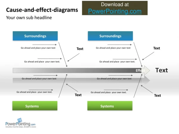
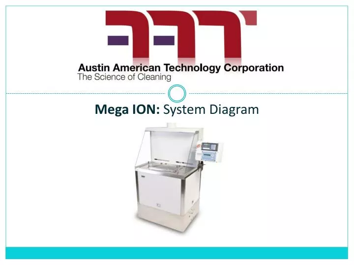
Mega ION: System Diagram. High Level Float. Process Chamber. HEAT (option). Nitrogen Dryer. S5. S1. Fill. S2. Wash. S2. Test. S3. RES. SENSOR. Drain. S4. S1. S5. Dry. IAC. S2. S4. P1. S3. S2. (. ). Low Level Float. Closed Fluid Reservoir. IONIC ABSORPTION CHAMBER.

Download Presentation

Mega ION: System Diagram

An Image/Link below is provided (as is) to download presentation Download Policy: Content on the Website is provided to you AS IS for your information and personal use and may not be sold / licensed / shared on other websites without getting consent from its author. Content is provided to you AS IS for your information and personal use only. Download presentation by click this link. While downloading, if for some reason you are not able to download a presentation, the publisher may have deleted the file from their server. During download, if you can't get a presentation, the file might be deleted by the publisher.

E N D

Presentation Transcript


  1. Mega ION: System Diagram

  2. High Level Float Process Chamber HEAT(option) Nitrogen Dryer S5 S1 Fill S2 Wash S2 Test S3 RES. SENSOR Drain S4 S1 S5 Dry IAC S2 S4 P1 S3 S2 ( ) Low Level Float Closed Fluid Reservoir IONIC ABSORPTION CHAMBER S1

  3. 高液位浮标 清洗腔室 加热 选件 氮气干燥 S5 S1 注入 S2 清洗 S2 测试 S3 电阻率 探头 排泄 S4 S1 S5 干燥 IAC S2 S4 P1 S3 S2 ( ) 低液位浮标 封闭的溶剂槽 离子吸附 腔室 S1

  4. GLOBAL REACH AND ON-SITE SERVICE CAPABILITY

More Related