Download
1 / 15
150 likes | 301 Views
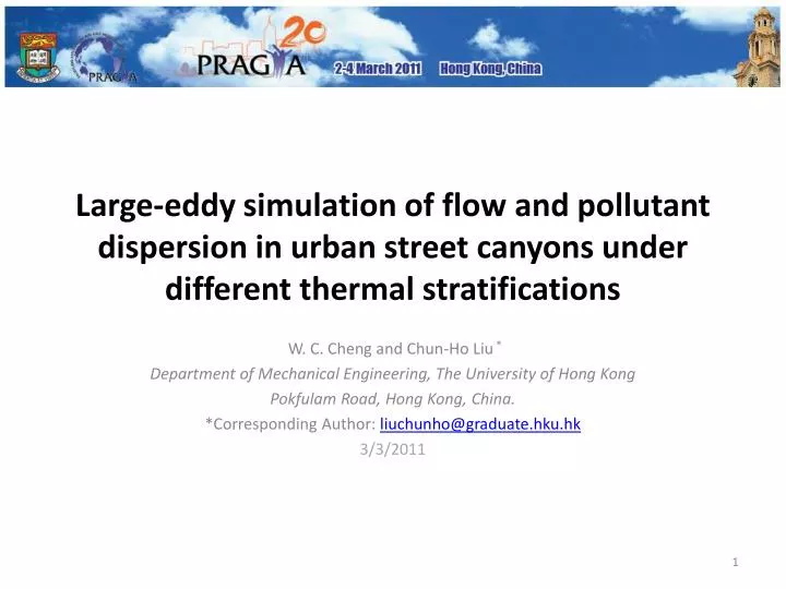
Large-eddy simulation of flow and pollutant dispersion in urban street canyons under different thermal stratifications . W. C. Cheng and Chun-Ho Liu * Department of Mechanical Engineering, The University of Hong Kong Pokfulam Road, Hong Kong, China.

E N D
Large-eddy simulation of flow and pollutant dispersion in urban street canyons under different thermal stratifications W. C. Cheng and Chun-Ho Liu * Department of Mechanical Engineering, The University of Hong Kong Pokfulam Road, Hong Kong, China. *Corresponding Author: liuchunho@graduate.hku.hk 3/3/2011
Content • Introduction • Methodology • Results and Discussions • Mean wind • Turbulence • Pollutant dispersion • Conclusions
Introduction • Urban street canyon is the canyon structure constructed by the buildings and streets geometry in urban area Figure 1. Urban street canyon (Berkowicz 2000)
The air inside street canyon is mainly driven by (1) the shear force by the free stream wind and (2) the buoyancy due to heating by solar radiation • The relative contributions of buoyancy to the shear stress can be quantified by the dimensionless number Richardson number (Ri) • Keep the Reynolds number (Re) constant • Assume the flow and pollutant removal patterns are function of Ri only
Methodology • Large-eddy simulation (LES), one equation subgrid-scale (SGS) model for turbulent kinetic energy (TKE) • OpenFOAM 1.6 • Wall function (Spalding 1962) for velocity • Boussinesq approximation for buoyancy • The simulations are performed in the HPCPOWER2 and GRIDPOINT Linux clusters of Computer Center of the University of Hong Kong
Computational Domain • Total number of mesh = 15 million • Finest grid near streets and buildings with height = 2.310-3h 5h 6h 5h Free stream flow (U0,q0) h b w Table 1. Number of element Buildings and streets heat source Q Figure 2. Computational domain
Re10000 • Rb =agh(q0- Q)/Uf2 • 5 sets of LESs with Rb = -0.11, -0.06, 0 , 0.18 and 0.35 • The results are spatial and temporal averaged using 100s of data with 0.1s interval.
Results and Discussion • Wind contours and the comparison with wind tunnel experiment Figure 3. Contour of mean velocity magnitude and streamlines in different thermal stabilities (a) Rb = 0.35, (b) Rb = 0.18, (c) Rb = 0, (d) Rb = -0.06 and (e) Rb = -0.11. Figure 4. Vertical profiles of u/Ufalong the centerline of the street canyon.
Maximum reverse wind speed and the locations Table 2. Shift of the location of maximum reversespeed from the center of the street surface. Figure 5. Maximum reverse wind speed (umax) in the street canyon. (a) Current LES and (b) Uehara et al. (2000).
Streamwise, spanwise and vertical velocity variances Figure 6. Contours of (i) u’u’1/2/Uf, (ii) v’v’1/2/Uf and (iii) w’w’1/2/Uf in different thermal stratifications: (a) Rb = 0.35, (b) Rb = 0.18, (c) Rb = 0, (d) Rb = -0.06 and (e) Rb = -0.11.
Velocity variances comparison Figure 7. Vertical profiles of (a) u’u’1/2/Ufand (b) w’w’1/2/Uf along the centerline of the street canyon: (i) Current LES; (ii) Uehara et al. (2000). for the current LES results, Rb = 0.35: Deep blue dashed line, Rb = 0.18: Light blue dashed line, Rb = 0: Black solid line, Rb = -0.06: Pink short dotted line and Rb = -0.11: Red dotted line.
Shear stress contours Figure 8. The contour u’w’/Uf2in different thermal stabilities: (a) Rb = 0.35, (b) Rb = 0.18, (c) Rb =0, (d) Rb = -0.06 and (e) Rb =-0.11. For the current results, Rb = 0.35: Deep blue dashed line, Rb = 0.18: Light blue dashed line, Rb = 0: Black solid line, Rb = -0.06: Pink short dotted line and Rb = -0.11: Red dotted line.
Shear stress comparison Figure 9. Vertical profiles of u’w’1/2/Uf along the centerline of the street canyon: (i) Current LES; (ii) Uehara et al. (2000). For the current LES results, Rb = 0.35: Deep blue dashed line, Rb = 0.18: Light blue dashed line, Rb = 0: Black solid line, Rb = -0.06: Pink short dotted line and Rb = -0.11: Red dotted line. Figure 10. Roof-level u’w’/Uf2 plotted against Rb. (a) Current LES and (b) Uehara et al. (2000).
Pollutant concentration contours and the retention time Figure 11. Contour of c/C0 in different thermal stabilities. (a) Rb = 0.35, (b) Rb = 0.18, (c) Rb = 0, (d) Rb = -0.06 and (e) Rb = -0.11. Figure 12. Pollutant retention time plotted against Rb.
Conclusions • The flow patterns are similar for neutral and unstable results and changes in flow patterns are observed in stable conditions because of the strong depression of mean wind at the lower leeward corner • Turbulence generally increases with decreasing Rb except increases of TKE in the center region of street canyon is observed in stable conditions • The pollutant concentration show strong dependence on the thermal stratifications and serious accumulation of pollutant is observed in stable conditions