Download
1 / 41
410 likes | 490 Views
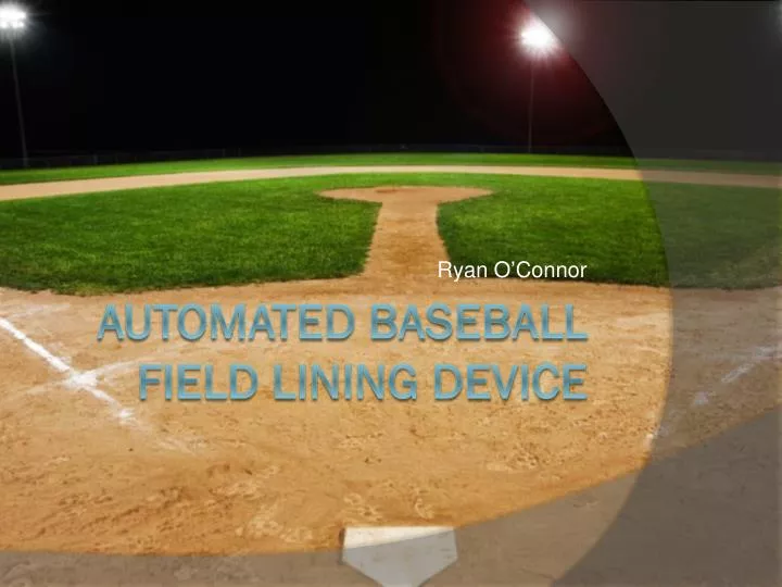
Ryan O’Connor. Automated Baseball Field Lining Device. The Problem.

E N D
Ryan O’Connor Automated Baseball Field Lining Device
The Problem • The problem identified is that it is difficult to effectively lay down straight and accurate foul lines on a baseball field, making it difficult for player and umpires to distinguish between batted balls which fall fair or foul down these lines. • The equipment used to draw these lines is heavy, difficult to push, and generally uncooperative
The Solution • I have devised a machine that uses electrical motors to pull a chassis along a guide-wire, allowing it to pull a basin of chalk and a can of spray paint for the dirt and grass portions of the line, respectively. • The wire would reach from home plate to the foul pole, and would be strung very tightly to minimize path deviation.
The Project • The Project was initially planned to be a production-based project with a functioning robot • The robot was to be built from steel components and a single AC motor that would be incorporated into a gearbox that would drive a pair of pulleys on the top of the machine.
The Project • The primary objective of this project is to produce a functioning robot system capable of traveling in a straight path while laying down chalk and spray paint for baseball foul lines
The Engineering • Electrical – The robot will be powered by a DC battery mounted on the chassis. This battery will be used to power the motor that will drive the gears that pull the robot along the guide wire • Mechanical – The motor will be incorporated into a gearbox that will allow for the pulley system to pull the robot along the wire
The Budget • The original budget for this project was about $50.00 • My plan was to use parts from my SRC project last year to build the chassis and gearbox • I would spend the $50 on scrap and sheet metal that would be used to build the superstructure • All chalk, paint, and the basin would be provided by the Landstown Baseball team
The Budget • Unfortunately, I had to wait until December to confirm whether or not I would be able to use the chassis • I was then informed that I could not • I then looked into potentially buying the parts myself
The Budget • The robot chassis would cost between $350 and $550 • Each high-torque motor would cost between $50 and $150 • The gears, hardware, and electrical supplies would total to approximately $50 • In total, a functioning machine would cost between $500 and $900 to build
The Budget • This budget made self-funding the project entirely unfeasible • I was then forced to reevaluate my Senior Design Project
The New Project • As such, I had to transition my functioning project to a series of 2D and 3D CADD drawings (Computer Aided Drafting and Design)
The Learning Curve • Unfortunately, in nearly four years at Landstown, I have never taken a CADD class, and have never used the intricate, advanced drafting software needed • As such, I had to teach myself how to use AutoCAD to produce 2D drawings • I also had to teach myself how to use Autodesk Inventor Professional to produce my 3D drawings and models
The Design Process • I began by designing the chassis for the robot, based on the GearsED • I measured the specifications from the GearsED chassis I used last year
The Design Process • I used these specifications to design a to-scale model of the chassis
The Design Process • I took these designs and created a 3D version, along with two axels and 4 wheels to complete the chassis
The Design Process • After completing the Chassis, I devised the superstructure of the robot
The Design Process • I again incorporated these designs into my 3D model of the chassis
The Design Process • After the Superstructure was complete, I designed a model of the motor that I would buy and utilize in my robot
The Design Process • I then took the motor and incorporated it into the superstructure assembly
The Design Process • Following completion of the superstructure, I began devising the chalk basin • I used the specs from the LHS Baseball team’s chalk basin for my model and created 2D drawings based on my measurements
The Design Process • After designing the components that would form the basin structure, I integrated them into a 3D model
The Design Process • I then created my own wheels to replace the stock wheels on the basin • These wheels would have low friction and high traction in both dirt and mud
The Design Process • I then added these wheels on low-friction axels mounted on the basin
The Design Process • I then had to devise a way of mounting the chalk basin to the chassis. • I custom-designed a piece that would do this
The Design Process • I then built a 3D model of this part and affixed it to the chassis
The Design Process • Next, I attached the Chalk Basin to the chassis via the custom basin mount
The Design Process • This left only the spray paint that would draw the outfield lines • Again, I had to engineer a custom piece that would mount the spray can • This piece would also need to be able to hold the can in the “on” position while it moves
The Design Process • I then incorporated this piece into the chassis
The Final Design • With all of the components assembled and integrated, the design was complete • The robot design is now capable of pulling itself along a guide wire • It is also capable of pulling a basin filled with chalk, as well as a can of spray paint