Download
1 / 24
240 likes | 383 Views
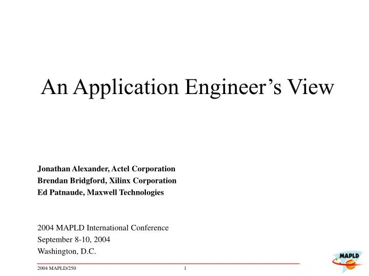
An Application Engineer’s View. Jonathan Alexander, Actel Corporation Brendan Bridgford, Xilinx Corporation Ed Patnaude, Maxwell Technologies 2004 MAPLD International Conference September 8-10, 2004 Washington, D.C. Jonathan Alexander Actel. Common HDL Coding Errors - 1.

E N D
An Application Engineer’s View Jonathan Alexander, Actel Corporation Brendan Bridgford, Xilinx Corporation Ed Patnaude, Maxwell Technologies 2004 MAPLD International Conference September 8-10, 2004 Washington, D.C.
Common HDL Coding Errors - 1 • Variable assignments are sensitive to order. • Variables are updated immediately • Signal assignments are order independent. • Signal assignments are scheduled Process (Clk) begin if (Clk’Event and Clk=‘1’) then Trgt1 <= In1 xor In2; Trgt2 <= Trgt1; Trgt3 <= Trgt2; end if; end process; Signal vTarg3 : std_logic; Process (Clk) Variable vTarg1, vTarg2: ... begin if (Clk’Event and Clk=‘1’) then vTrgt1 := In1 xor In2; vTrgt2 := vTrgt1; vTrgt3 <= vTrgt2; end if; end process; Process (Clk) Variable vTarg1, vTarg2 : ... begin if (Clk’Event and Clk=‘1’) then Trgt3 <= vTrgt2; vTrgt2 := vTrgt1; vTrgt1 := In1 xor In2; end if; end process; Process (Clk) begin if (Clk’Event and Clk=‘1’) then Trgt2 <= Trgt1; Trgt3 <= Trgt2; Trgt1 <= In1 xor In2; end if; end process; Trgt3 Trgt3 Trgt3
Latches • Accidental Latch Inferring • Latches are prone to data corruption due to input glitches, and timing analysis is quite difficult. Latches should be avoided • Verilog combinatorial always blocks must always have a “default” statement to avoid latch inferring • This especially applies to state machines. • Example: Without Default Statement: Common HDL Coding Errors - 2 always @(posedge clk) begin state <= statenext; end always @(state,data) begin: my_register case (state) 2'b00 : begin aaa = data; bbb = 0; ccc = data; statenext = 2'b01; end 2'b01 : begin aaa = 1; bbb = 0; ccc = data; statenext = 2'b10; end 2'b10 : begin aaa = data; bbb = 1; ccc = data; statenext = 2'b00; end endcase end //my_register
Common HDL Coding Errors - 2 (cont’d) • Example: With Default Statement always @(posedge clk) begin state <= statenext; end always @(state,data) begin: my_register case (state) 2'b00 : begin aaa = data; bbb = 0; ccc = data; statenext = 2'b01; end 2'b01 : begin aaa = 1; bbb = 0; ccc = data; statenext = 2'b10; end 2'b10 : begin aaa = data; bbb = 1; ccc = data; statenext = 2'b00; end default : begin aaa = data; bbb = 1; ccc = data; statenext = 2'b00; end endcase end //my_register Flip-Flops only
Maintaining Data Integrity in EEPROM’s What are some of the sources of data corruption ? • Data corruption in EEPROM’s occurs most often during power on and power off sequencing due to improper hardware and/or software implementation. • Loss of power before a write cycle is completed can result in corrupted data. • Software errors can lead to improper timing, buss contention, prematurely halting a write cycle, or initiating inadvertent writes to the EEPROM. • Exceeding the write endurance of the device can damage the memory cells leaving them un-programmable.
Maintaining Data Integrity in EEPROM’s What is the likelihood of having data corruption occur? The question should be: “How do I maintain data integrity? • Implement power supervisory circuitry to control the hardware during power up and power down sequencing. • Enable Software Data Protection to prevent inadvertent writes. • Always verify the data after a write has occurred. • Use EDAC to identify and correct corrupted data. • Use redundant memory to increase system reliability.
Application Engineer’s View Brendan Bridgford Xilinx Aerospace and Defense
Avoiding Timing Problems in TMR Designs - 1 • TMR systems in re-configurable devices have special timing needs • State machines: Voter insertion creates cross-domain timing paths
Non-TMR State Machine Timing Constraints NET clk TNM_NET = “CLK”; TIMESPEC “TS_CLK_IN” = PERIOD “CLOCK_IN” 10ns; The data path FROM synchronous elements TO synchronous elements … on the CLK net must be constrained
TMR State Machine Timing Constraints Now, the data paths FROM synchronous elements in EACH clock domain TO synchronous elements in EACH clock domain … must be constrained CLK_TR0 CLK_TR1 CLK_TR2
TMR State Machine Timing Constraints PROBLEM: Three independent period constraints won’t cover cross-domain paths. CLK_TR0 NET CLK_TR0 TNM_NET = “CLK_TR0”; TIMESPEC “TS_CLK_TR0_IN” = PERIOD “CLK_TR0_IN” 10ns; CLK_TR1 NET CLK_TR1 TNM_NET = “CLK_TR1”; TIMESPEC “TS_CLK_TR1_IN” = PERIOD “CLK_TR1_IN” 10ns; CLK_TR2 NET CLK_TR2 TNM_NET = “CLK_TR2”; TIMESPEC “TS_CLK_TR2_IN” = PERIOD “CLK_TR2_IN” 10ns;
TMR State Machine Timing Constraints SOLUTION: Use “related” PERIOD constraints CLK_TR0 NET “clk_TR0” TNM_NET = “clk_TR0”; TIMESPEC “TS_clk_TR0” = PERIOD “clk_TR0” 10ns; NET “clk_TR1” TNM_NET = “clk_TR1”; TIMESPEC “TS_clk_TR1” = PERIOD “clk_TR1” TS_clk_TR0 * 1.0; NET “clk_TR1” TNM_NET = “clk_TR2”; TIMESPEC “TS_clk_TR2” = PERIOD “clk_TR2” TS_clk_TR0 * 1.0; CLK_TR1 CLK_TR2
Testing and Troubleshooting Techniques - 1 • FPGA Debugging Issue • FPGA designs typically do not include sophisticated self-diagnostics • Pre-defined test point consume I/Os • Test circuits consume valuable gates • How to observe and debug FPGA faults? • Silicon Explorer for Antifuse FPGAs • Dedicated, built-in architecture gives access to virtually every internal node in the FPGA • Nodes can be changed on the fly while device is operating at full speed • Up to 4 nodes can be monitored simultaneously • Uses JTAG input pins for node addressing • Flexible I/Os can toggle between user output and Probe outputs • No FPGA gates or routing consumed • No additional design required
Testing and Troubleshooting Techniques - 2 • Active Probes • Use active probes when you want to observe signals with high frequency components (ie noise) • They provide very low capacitive loading (<1pF) • Passive probes often will filter high frequency components • Real-life Example: • Flip-Flop intermittently double-shifts data. • Passive probe on external clock did not reveal anything, however failure never occurred while probing with passive probes
Testing and Troubleshooting Techniques - 2(cont’d) • Differential Probes or Signal Subtration • Differential probes allow users to measure the difference between two nodes • Most oscilloscopes allow users to subtract signals to calculate the difference between two or more nodes • Both solutions are useful when measuring component power supply noise with respect to component ground • VCC alone may not cause an out of spec condition • GND alone may not cause an out of spec condition • VCC - GND may exceed spec • Similar situation can apply when measuring VIN with respect to Ground (when ground bounce is coincident with reflections)
Avoiding Timing Problems in TMR Designs - 2 • TMR systems in re-configurable devices have special timing needs 2. PCB-induced phase shift between clock domains must be minimized
Phase shift between Clock Domains - Description Clock Net FPGA Clock Pulse (ideal) Ideally, all clock domains are in perfect phase alignment In practice, clock domains can be phase shifted with respect to each other - due mainly to PCB layout – “external” factors - “internal” factors can only contribute a few picoseconds Clock Pulse (actual)
Phase Shift between Clock Domains - Consequences Output Clock Net FPGA VOTER • If clock domains are grossly out of phase, voter output will be momentarily incorrect for a portion of each clock cycle. • -TMR State Machines may not operate correctly • Even if design operates correctly, SEU immunity will be reduced
Phase Shift between Clock Domains - Solution Output Clock Net FPGA VOTER • Ensure redundant clock traces are of equal length! • Signal Integrity simulation should be performed to ensure that clock arrivals are as close as possible.