Download
1 / 30
340 likes | 699 Views
PET – positron emission tomography. Electromagnetic Spectrum. PET – positron emission tomography. Inject Patient with Radioactive Drug. Late 1960’s Drug travels to targeted site Drug emits ( +) positrons (basically a positively charged electron)

E N D
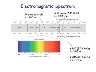
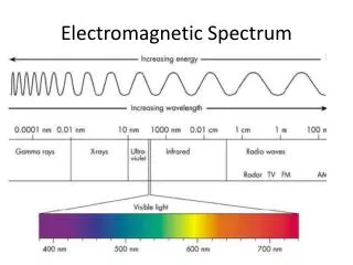
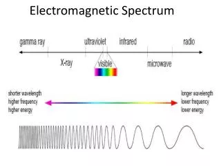
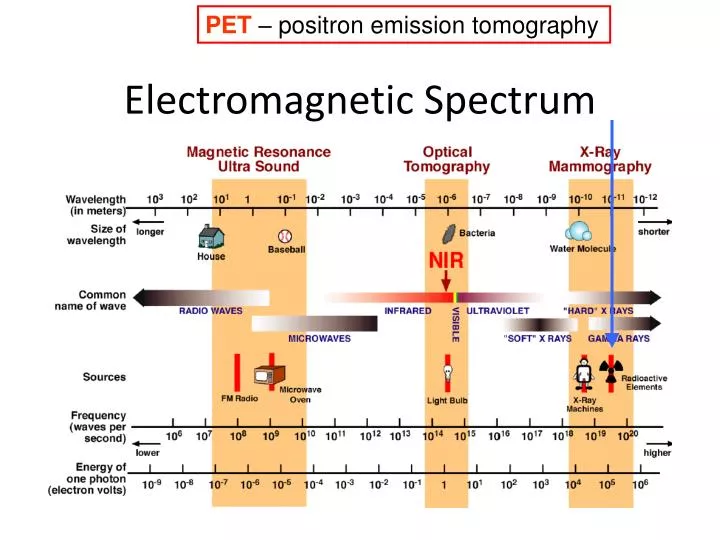
PET – positron emission tomography Electromagnetic Spectrum
PET – positron emission tomography Inject Patient with Radioactive Drug Late 1960’s Drug travels to targeted site Drug emits (+) positrons (basically a positively charged electron) FDG - Fluorodeoxyglucose (most common drug) (F18 – + emitter – two hour half-life) goes to metabolically active sites (tumor) Advantage functional imaging Disadvantage some ionizing radiation low resolution (4mm x 4mm x 4mm) need to make/buy FDG (cyclotron)
PET – positron emission tomography • β+ decay, positron travels several mm and collides with an electron • produce a pair of annihilation photons (511kev, 180o) • simultaneous detection 180o apart
PET/CT - together PET (Xray) CT Pet & CT PET
Hemodynamic & Metabolic Imaging (C15 O2 by inhalation or H215 O i.v.) to measure cerebral blood flow (CBF), cerebral blood volume (CBV) and cerebral metabolic rate for oxygen (CMRO2) using the Kety-Schmidt model derived from the Costly and difficult to perform in emergency settings-reserved mainly for select patients and for clinical research C15 F18 Coles et al., JCBFM 29:965-975, 2009
Back to MRI Where were we?
Model of Head Coil Excite Listen RF B0
Excitation – axis’s are Primed Reference Frame (axis's always primed … sometimes viewed from the lab frame … sometimes viewed from the primed frame) Excitation magnetic Field produced by EM radiation White vector – collective magnetic moment for one voxel Blue vector – excitation magnetic field B1 – generates tipping torque Thanks S. Cohen http://www.youtube.com/watch?v=KtWnmFg-u5g
(probably choose w=w0=γB0) Excitation magnetic Field produced by EM radiation Some math to describe motion lab reference frame – Bloch Equations Probably want the rotating reference frame to rotate at w=w0=γB0 One simple solution would just be precession with Myαcos (w0t) and Mxα sin (w0t)
Excitation magnetic Field produced by EM radiation Some math to describe motion lab reference frame – Bloch Equations Exponential decay with solutions (quick glance) Myor Mxαexp (-t/T2)
Lab Reference Frame Model of Head Coil Voltage proportional to flux change WHY loose signal?
Some math to describe motion lab reference frame – Bloch Equations Probably want the rotating reference frame to rotate at w=w0=γB0 Note – this is equation in your book with w0 = γB0 It is in the rotating reference frame!! In rotating reference frame RF (B1 applied to x’ axis) rotates magnetic moment M around X axis We’ve seen these solutions already! Mz’αcos (w1t) and My’α sin (w1t)
Excitation – axis’s are Primed Reference Frame (axis's always primed … sometimes viewed from the lab frame … sometimes viewed from the primed frame) FLIP Angle White vector – collective magnetic moment for one voxel Blue vector – excitation magnetic field B1 – generates tipping torque Thanks S. Cohen http://www.youtube.com/watch?v=KtWnmFg-u5g
T2decay ……….. Shouldn’t it be T2* decay? T2* decay of Transverse Magnetization (time = T2*= 33% of signal remains) exp (-t/T2*) ‘ Dephasing
Transverse magnetization decay due to magnetic field fluctuations In time or space T2* transverse decay due to both T2 and T2’ effects T2’ transverse decay part due to inhomogieties that are that are due to local field inhomogenieties (constant in time) – bad news – we can fix T2 transverse decay due to inhomogieties that are specific to tissue types (varies with time) (spin-spin interaction) – good news – we can't “fix” 1/T2* = 1/T2’ + 1/T2 signal strength = M0(exp(-t/T2*)) Starting magnetization after 90 pulse
Think briefly about T2’ “bad” starting field B0 ( extreme example) usually we correct for T2’ = does not show up in image air voxel (glass of water) B0 too large (precess faster) B0 ok in (~3ms) the signal is destroyed due to T2* T2 image T2* image
Think about T2 (usually more interesting) SIGNAL exp (-t/T2) fat CSF (watery) T2~ 60ms 800ms T2*~ 5ms 10ms (note T2* is magnet dependent) exp (-t/T2*) TIME 63 MHz (1.5T Trio)
What causes T2 transverse magnetization decay (spin-spin)? Varies with time as hydrogen moves around, rotation, vibration, translation. slow fast in (~100ms) the signal is destroyed due to T2
Water – vibrations states of water (1013 Hz) and fast tumbling rate make this effect “weak” b/c effect gets averaged out = real long T2 Water protons around “stuff” – slows tumbling and translations make T2 effect more evident = long T2 Fat – protons exposed to neighboring protons on fat and neighboring fat for “long” time – T2 effect is more noticeable = shorter T2 Proteins – protons exposed to neighboring protons on protein for “very long” time - strong T2 effect = short T2 Solids – protons exposed to neighboring protons for “very very long time” - T2 too short for imaging (T1 is really long as well) note: long, very long, very very long, etc does not mean they are stationary
How to make a T2 or T2*contrast image? Listen to protons here! Voxel in tissue #2 Voxel in tissue #1 Jack Pot to being bright on T2 image
T2-Weighting (SE) • CSF (fluid) bright • GM gray • WM dark
Some math to describe motion lab reference frame – Bloch Equations Probably want the rotating reference frame to rotate at w=w0=γB0 Note – this is equation in your book with w0 = γB0 It is in the rotating reference frame!! In rotating reference frame RF (B1 applied to x’ axis) rotates magnetic moment M around X axis Exponential recovery!! Mzα [1-exp (-t/T1)]
Rotating Frame ‘ ‘ ‘ ‘
Making an image with T1 contrast Listen to protons here! Voxel in tissue #2 Voxel in tissue #1 Jack Pot to being bright on T2 image
T1-Weighting (SE) • CSF (fluid) dark • WM bright • GM gray
How does the longitudinal magnetization recover (T1)? Two basic water types in our body Bound (rotates close Larmor frequency) Free (rotates a bit too fast) Jack Pot to being bright on T1 image tumbling velocity Just right (almost) Too slow Too fast
Tickle a nucleus at the Larmor frequency for fastest signal recovery!! http://www.revisemri.com/questions/misc/shorter_t1_tissues
At a main field of 1.5 T Note : T1s get larger at 3T b/c Lamor frequency farther from rotational freq. of molecules