Download
1 / 18
190 likes | 433 Views
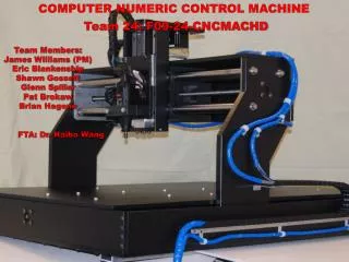
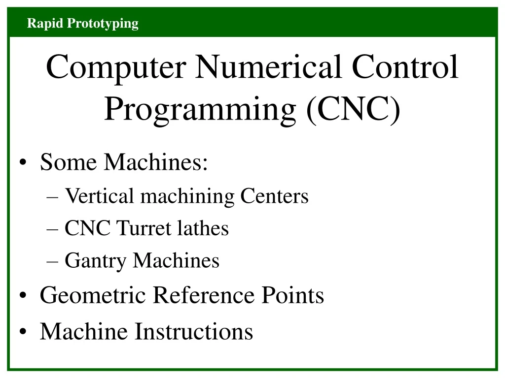
Computer Numerical Control Programming (CNC). Some Machines: Vertical machining Centers CNC Turret lathes Gantry Machines Geometric Reference Points Machine Instructions. Vertical Machining Centers. CNC Turret Lathe. CNC Gantry Machines. Machine Reference Points.

E N D
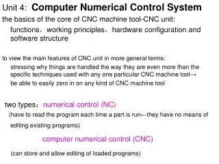
Computer Numerical Control Programming (CNC) • Some Machines: • Vertical machining Centers • CNC Turret lathes • Gantry Machines • Geometric Reference Points • Machine Instructions
Machine Reference Points • Machine Start or “reference” home position on startup of controller • Machine Zeropoint: Front left corner of table: the machine cannot actually get here: position must be “offset”
Workpiece Zeropoint: PSO Location: x = 0.0 y = 0.0 z = 0.0 Determined by operator in PSO register called by: G54, G55, G57, G58 or G59
Tool Offset: TO register • Used to correct for length of tool when they are replaced. • Note: for our lab the PSO an TO are preset: please do not change them.
Programming Instructions • Address: letter giving specific instruction: G, M, S, F, T • Word: The combination of letter and subsequent number: G00, M30, S3000 • Blocks: Line numbers proceeding all words: N0010, N0020, etc.
G70: inches G53: clear registers G55: offset register G94: feed in/min M30: End of Program T0000: tool number and offset register: T0717 S0000: Machine rpm: S3000 Machine Instructions
Machine Instructions • F000: Feed rate (we use in/min) • G00: Rapid linear traverse • G01: Linear move: must have F address on same line, or a proceeding line. G00 “calls off” a F address.
Machine Instructions • G02: CW Circular InterpolationG03: CCW Circular Interpolation • I and J axis are used to describe the center of arc radius. The location of I,J origin is described relative to the arc start point P1 • NOTE: Both I and J must be called out, even if one has a value of 0.0
Describing an Arc j P2: 1.125, 1.625 R= 0.375 i= 0.0 j= 0.375 i P1: 0.75, 1.25 N0000 G03 X1.125 Y1.625 I0.0 J0.375
G03 CCW Circular j R= 0.375 P1: 0.75, 1.25 i i= 0.375 j= 0.0 P2: 1.125, 0.875 N0000 G03 X1.125 Y0.875 I0.375 J0.0
G02 with (-) i value j i= -0.375 j= 0.0 P1: 0.75, 1.25 i P2: 0.375, 0.875 N0000 G02 X0.375 Y0.875 I-0.375 J0.0
Other Circular Moves • Half Circles • Complete circles • Partial Arcs