Download
1 / 38
390 likes | 617 Views
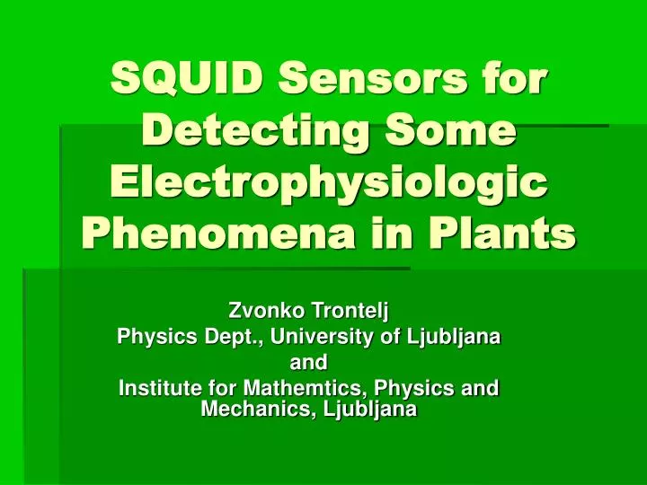
SQUID Sensors for Detecting Some Electrophysiologic Phenomena in Plants. Zvonko Trontelj Physics Dept., University of Ljubljana and Institute for Mathemtics, Physics and Mechanics, Ljubljana. Outline of talk. Introduction On SQUID sensor

E N D
SQUID Sensors for Detecting Some Electrophysiologic Phenomena in Plants Zvonko Trontelj Physics Dept., University of Ljubljana and Institute for Mathemtics, Physics and Mechanics, Ljubljana
Outline of talk • Introduction • On SQUID sensor • Basic steps in data analysis and modelingof sources of bioelectric activity • Examples from the world of plants: • a) Chara corallina (single cellstudies) • b) Vicia faba(plant injury study) • Conclusions
Objectives: • To apply SQUID(s) in order to obtain the noninvasive information on: a)ionic currents in electrically stimulat.Chara corallina, b) the influence of visible light on AP and on AC in C.c. and to relate the ionic kinetics to chemical nature of AP. c) the injury induced ionic currents in the plant organs - leaves in the higher developed plant Vicia faba. • To model the transmembrane pot. difference under different conditions and to support the suggest. hypoth. of light action on the cytoplasmic Ca ion. conc.
SQUID sensors • What is SQUID? • What they offer to us? • Where we can use them? • Why SQUID sensors in electrophysiology?
Ad 1 and Ad 2 • Superconducting QUantum Interference Device • Magnetic flux-to-voltage convertor (the most sensitive sensor for quasi dc magnet. fields m.) • Measured m. field; via Amper’s law the source • Based on 3 facts described by QM - superconductivity with Cooper pairs - C. pair tunneling - m. flux quantization
Ad 3 and ad Ad 4 M. flux has to be transp.to SQUID SQUID has to be in m. shielded env.
Basic steps in analysis and modelling of current sources in living matter • Distribution of ionic currents in tissue. Complicated • Direct and inverse problem • The direct problem – a unique solution • F T = ZTE FE • The inverse problem is ill-posed problem • F E = ZET FT • Simple geometry – analyt. solutions, otherweise modeling
Simple geometry • Single cylindrically shaped cell (1D case) • DF = 0 • Bound. cond.: Fm(z) = Fi (a,z) – Fe (a,z) • n.Ji (a,z) = n.Je(a,z)
Simple geometry (contin.) • From Ampere law: • Bi = Integr. [G(r,a,z – z’)Ji(a,z’)]dz • Applying the Fourier and the inverse Fourier transformations one can come from potential to mag. field and v.a.v.
Some methods in modeling of current sources • Current multipole expansion • Current distribution with the minimum norm estimation • Covariance method (to extract the dc component of the measured modulated magnetic field data)
Examples from the world of plants: • a) Simple plant cell – Internodal cell of green algae Chara corallina
Multi-SQUID measuring configuration (37 channels) -schematically
C.Corallina intern. cell: stimulus location and measuring points; intra-,extracell. curr.; m. field
The time evolution of magnetic field (vert. comp.) measured in 37 points above the C. corallina
The isofield lines representation • 3 particular time values (1.3s, 1.6s, 1.9s) after the stimulus
The isof. representation (at 1.4s, 2.5s, 3.6s); model. calc. of current dipol and current density along the C.c. intern. c.
Spreading of excitation along the cell: v ~ 4cm/s Conductivity: si = 1.2 W -1m -1 , sex = 0.025 W -1m -1 Length of the depolarized area: l ~ 50 mm Maximal intracellular current: Ii = 1mA Some results
Examples from the world of plants: b) the influence of visible light on AP and onB in Chara corallina: The chemical nature of AP obtained from the non-invasive observation (by SQUID microscope) of the intracellular current under the influence of light
SQUID microscope prepared for the C.c. inernodal cell studies (schematically)
We measure: Electric AP K+ anesthesia technique Magnetic field SQUID Microscope Both measurements are simultaneous Part of SQUID microscope and C.c. internodal cell holder
AP as function of light exposure • Light ON 20 min • Light ON 60min Protocol of the C.c.experiment with white light illumination • Light OFF reference • Light ON 10 min
The influence of ilumination on the measured B and AP of electrically stimulated C.c. internodal cell
Model which explains the illumination experiment in the context of 2nd messenger system [Ca2+]c is altered under the influence of light/dark transitions (Miller@Sanders 1987) AP can be described by an electrically stimulated release of Ca2+ from internal store: a) the voltage depend. synthesis/breakdown of the 2nd mesenger IP3 . b) the joint action of IP3 and Ca2+ on the gating of the receptor channels, which conduct Ca2+ release from internal stores. c) modification: cells move excess Ca2+ from the cytoplasm back into internal stores by an endogeneous Ca2+ pump system (described by the Hill function. Quantitative evaluation follows the Othmer model.
Simulated [Ca+2]c transients in response to a single electrical stimulation
Some results • Assuming that the activation of the Cl- channels, that cause the depolarization, is the direct consequence of the change in [Ca2+]c , the measurementsquantitavely agree well with the model.
Examples from the world of plants: c) the injury induced ionic currents in the plant organs - leaves in the higher developed plant Vicia faba, detected magnetically by the multichannel SQUID system.
Time evolution of magnetic field in all channels:panel A 15 min. before injury, panel B 1-16 min after injury, panel C time evolution of field RMS value, panels D end E isofield maps 10 min before and 1.5 min after injury.
Some results All measured injured Vicia f. plants responded to injuries with detectable quasi-d.c. magnetic signals. Large injury leads to easily localizable current source of dipolar pattern. The characteristic time delay is about 10 min. No long-distance spreading of electrical activity was generally observed.
Conclusions • Magnetic measurements offer also in the world of single plant cells and plants valuable noninvasive information. • Both, multichannel SQUID system and SQUID microscope can be applied. The last option offers good spatial resolution. • Results from magnetic measurements can be considered as complementary to the existing electric measurements in plants. • SQUID measurements provide direct information on the behavior of ionic currents.
Participating Researchers University of Ljubljana: Vojko Jazbinsek, Matjaz Slibar, Ales Stampfl, Robert Zorec PTB Berlin: Sergio Erné (now at Univ. Ulm), Wolfgang Mueller, Gerd Wuebbeler TU Darmstadt: Gerhard Thiel, Michael Wacke Vanderbilt University: Franz Baudenbacher, Luis Fong, Jenny Holzer, John Wikswo