Download
1 / 38
380 likes | 497 Views
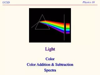
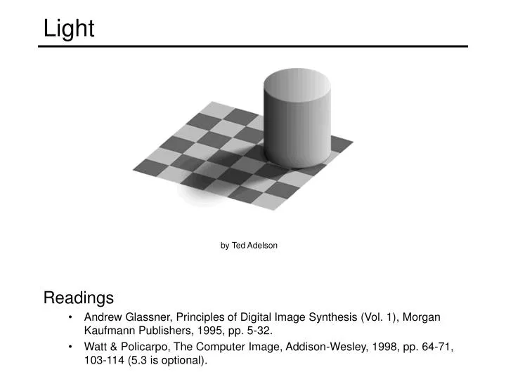
Light. Readings Andrew Glassner, Principles of Digital Image Synthesis (Vol. 1), Morgan Kaufmann Publishers, 1995, pp. 5-32. Watt & Policarpo, The Computer Image, Addison-Wesley, 1998, pp. 64-71, 103-114 (5.3 is optional). by Ted Adelson. Properties of light. Today What is light?

E N D
Light • Readings • Andrew Glassner, Principles of Digital Image Synthesis (Vol. 1), Morgan Kaufmann Publishers, 1995, pp. 5-32. • Watt & Policarpo, The Computer Image, Addison-Wesley, 1998, pp. 64-71, 103-114 (5.3 is optional). by Ted Adelson
Properties of light • Today • What is light? • How do we measure it? • How does light propagate? • How does light interact with matter?
What is light? • Electromagnetic radiation (EMR) moving along rays in space • R(l) is EMR, measured in units of power (watts) • l is wavelength • Light field • We can describe all of the light in the scene by specifying the radiation (or “radiance” along all light rays) arriving at every point in space and from every direction
t is not time (different from above t !) • The light field • Assume radiance does not change along a ray • what does this assume about the world? • Parameterize rays by intersection with two planes: • Usually drop l and time parameters • How could you capture a light field? The light field • Known as the plenoptic function • If you know R, you can predict how the scene would appear from any viewpoint. How?
More info on light fields • If you’re interested to read more: • The plenoptic function • Original reference: E. Adelson and J. Bergen, "The Plenoptic Function and the Elements of Early Vision," in M. Landy and J. A. Movshon, (eds) Computational Models of Visual Processing, MIT Press 1991. • L. McMillan and G. Bishop, “Plenoptic Modeling: An Image-Based Rendering System”, Proc. SIGGRAPH, 1995, pp. 39-46. • The light field • M. Levoy and P. Hanrahan, “Light Field Rendering”, Proc SIGGRAPH 96, pp. 31-42. • S. J. Gortler, R. Grzeszczuk, R. Szeliski, and M. F. Cohen, "The lumigraph," in Proc. SIGGRAPH, 1996, pp. 43-54. show video
What is light? • Electromagnetic radiation (EMR) moving along rays in space • R(l) is EMR, measured in units of power (watts) • l is wavelength • Perceiving light • How do we convert radiation into “color”? • What part of the spectrum do we see?
The visible light spectrum • We “see” electromagnetic radiation in a range of wavelengths
Light spectrum • The appearance of light depends on its power spectrum • How much power (or energy) at each wavelength daylight tungsten bulb • Our visual system converts a light spectrum into “color” • This is a rather complex transformation
The human visual system • Color perception • Light hits the retina, which contains photosensitive cells • rods and cones • These cells convert the spectrum into a few discrete values
Density of rods and cones • Rods and cones are non-uniformly distributed on the retina • Rods responsible for intensity, cones responsible for color • Fovea - Small region (1 or 2°) at the center of the visual field containing the highest density of cones (and no rods). • Less visual acuity in the periphery—many rods wired to the same neuron
Demonstrations of visual acuity • With one eye shut, at the right distance, all of these letters should appear equally legible (Glassner, 1.7).
Demonstrations of visual acuity • With left eye shut, look at the cross on the left. At the right distance, the circle on the right should disappear (Glassner, 1.8).
Brightness contrast and constancy • The apparent brightness depends on the surrounding region • brightness contrast: a constant colored region seem lighter or darker depending on the surround: • http://www.sandlotscience.com/Contrast/CheckerBoard_illusion.htm • brightness constancy: a surface looks the same under widely varying lighting conditions.
Light response is nonlinear • Our visual system has a large dynamic range • We can resolve both light and dark things at the same time • One mechanism for achieving this is that we sense light intensity on a logarithmic scale • an exponential intensity ramp will be seen as a linear ramp • Another mechanism is adaptation • rods and cones adapt to be more sensitive in low light, less sensitive in bright light.
After images • Tired photoreceptors • Send out negative response after a strong stimulus http://www.sandlotscience.com/Aftereffects/Rotating_Spiral.htm
Color perception • Three types of cones • Each is sensitive in a different region of the spectrum • but regions overlap • Short (S) corresponds to blue • Medium (M) corresponds to green • Long (L) corresponds to red • Different sensitivities: we are more sensitive to green than red • varies from person to person (and with age) • Colorblindness—deficiency in at least one type of cone L response curve
M L S Color perception • Rods and cones act as filters on the spectrum • To get the output of a filter, multiply its response curve by the spectrum, integrate over all wavelengths • Each cone yields one number • Q: How can we represent an entire spectrum with 3 numbers? Power Wavelength • A: We can’t! Most of the information is lost. • As a result, two different spectra may appear indistinguishable • such spectra are known as metamers • http://www.cs.brown.edu/exploratories/freeSoftware/repository/edu/brown/cs/exploratories/applets/spectrum/metamers_guide.html
Perception summary • The mapping from radiance to perceived color is quite complex! • We throw away most of the data • We apply a logarithm • Brightness affected by pupil size • Brightness contrast and constancy effects • Afterimages
Camera response function • Now how about the mapping from radiance to pixels? • It’s also complex, but better understood • This mapping known as the film or camera response function • How can we recover radiance values given pixel values? • Why should we care? • Useful if we want to estimate material properties • Shape from shading requires radiance • Enables creating high dynamic range images • What does the response function depend on?
Recovering the camera response • Method 1 • Carefully model every step in the pipeline • measure aperture, model film, digitizer, etc. • this is *really* hard to get right • Method 2 • Calibrate (estimate) the response function • Image several objects with known radiance • Measure the pixel values • Fit a function • Find the inverse: maps pixel intensity to radiance pixel intensity = response curve radiance
pixel intensity = response curve exposure radiance * time = Recovering the camera response • Method 3 • Calibrate the response function from several images • Consider taking images with shutter speeds 1/1000, 1/100, 1/10, and 1 • Q: What is the relationship between the radiance or pixel values in consecutive images? • A: 10 times as much radiance • Can use this to recover the camera response function • For more info • P. E. Debevec and J. Malik. Recovering High Dynamic Range Radiance Maps from Photographs. In SIGGRAPH 97, August 1997
High dynamic range imaging • Techniques • Debevec: http://www.debevec.org/Research/HDR/ • Columbia: http://www.cs.columbia.edu/CAVE/tomoo/RRHomePage/rrgallery.html
Light sources • Basic types • point source • directional source • a point source that is infinitely far away • area source • a union of point sources • More generally • a light field can describe *any* distribution of light sources
The interaction of light and matter • What happens when a light ray hits a point on an object? • Some of the light gets absorbed • converted to other forms of energy (e.g., heat) • Some gets transmitted through the object • possibly bent, through “refraction” • Some gets reflected • as we saw before, it could be reflected in multiple directions at once • Let’s consider the case of reflection in detail • In the most general case, a single incoming ray could be reflected in all directions. How can we describe the amount of light reflected in each direction?
The BRDF • The Bidirectional Reflection Distribution Function • Given an incoming ray and outgoing raywhat proportion of the incoming light is reflected along outgoing ray? surface normal Answer given by the BRDF:
Diffuse reflection • Diffuse reflection • Dull, matte surfaces like chalk or latex paint • Microfacets scatter incoming light randomly • Effect is that light is reflected equally in all directions
Lambert’s Law: BRDF for Lambertian surface L, N, V unit vectors Ie = outgoing radiance Ii = incoming radiance Diffuse reflection • Diffuse reflection governed by Lambert’s law • Viewed brightness does not depend on viewing direction • Brightness does depend on direction of illumination • This is the model most often used in computer vision
Near-perfect mirrors have a highlight around R • common model: Specular reflection • For a perfect mirror, light is reflected about N
Moving the light source • Changing ns Specular reflection
Phong illumination model • Phong approximation of surface reflectance • Assume reflectance is modeled by three components • Diffuse term • Specular term • Ambient term (to compensate for inter-reflected light) L, N, V unit vectors Ie = outgoing radiance Ii = incoming radiance Ia = ambient light ka = ambient light reflectance factor (x)+ = max(x, 0)
design by Greg Ward Measuring the BRDF • Gonioreflectometer • Device for capturing the BRDF by moving a camera + light source • Need careful control of illumination, environment traditional
Columbia-Utrecht Database • Captured BRDF models for a variety of materials • http://www.cs.columbia.edu/CAVE/curet/.index.html