Download
1 / 15
150 likes | 303 Views
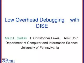
Low Overhead Pilot Structures. Igor Tolochko and Mike Faulkner, ATcrc, Victoria University mf@ee.vu.edu.au. RX 1. PA 3. PA Mt. PA 2. PA 1. RX 2. RX 3. RX Mr. MIMO System. A1. Channel Estimatiom Mt * Mr paths

E N D
Low Overhead Pilot Structures Igor Tolochko and Mike Faulkner, ATcrc, Victoria University mf@ee.vu.edu.au M.Faulkner, ATcrc
RX 1 PA 3 PA Mt PA 2 PA 1 RX 2 RX 3 RX Mr MIMO System A1 • Channel Estimatiom • Mt * Mr paths • S is the total transmit power: Tx power / antenna = S/Mt (equal power) • SNR is the receiver signal to noise ratio • MSE is the channel estimate error • Goal Estimate all Paths With the Minimum Overhead A2 A3 AMt M.Faulkner, ATcrc
Channel Estimation Requirements SISO Coherent Detection • Mt x Mr MIMO requires Mt orthogonal pilots • Time orthogonality • Frequency • Code • Low Pilot Overhead • Low Complexity • Low implementation (SNR) loss (low mean squared error) • MSE(channel) << SNR (data) • MSE < SNR -3dB (for 11a) SNR loss <= 1.76dB M.Faulkner, ATcrc
Time Orthogonal Frequency Time Interleaved Long (TIL) Pilots cp cp cp AMt AMt A1 A1 A2 A2 Sub-carriers • One Transmitter at a time • Each PA must provide the full power, S, during pilot transmission • Overhead 2Mt symbols per packet • Simple LS processing for MSE=0.5N (-3dB) • 11a Compatibility by inserting the ‘signal’ symbol after the first long, P(1), and transmitting it on A1 as per Jan Boer et al [2] AMt AMt A1 A1 A2 A2 AMt AMt A1 A1 A2 A2 8 s 8 s 8 s P(2) P(1) P(Mt) Time M.Faulkner, ATcrc
Code Orthogonality Code Interleaved Long (CIL) Pilots cp cp • All Tx at same time • P(k)= k’th pilot • PA power of S/Mt during pilot transmission • Overhead 2Mt symbols per packet • Simple LS processing for MSE=0.5N (-3dB) • 11a compatibility by inserting the ‘signal’ symbol after the first long symbol P(1) and transmitting it using co-transmission on A1 and A2 • Example Mt=2 • Walsh like • Can be expanded to Mt antennas • (low detection complexity if Mt=2,4,8) A1+A2 A1-A2 Sub-carriers A1+A2 A1-A2 A1+A2 A1-A2 8 s 8 s P(2) P(1) M.Faulkner, ATcrc
Frequency Orthogonality Frequency Interleaved Long (FIL) Pilots cp A1 • All Tx active, but not in the same frequency bin • PA power of S/Mt during pilot transmission • Overhead of 2 symbols (1 long) per packet … but MSE=0.5N + interpolation error …. too high?? • Might need Longer Pilots, More Pilots or Frequency Domain Processing to reduce MSE. • Simulations of Interpolation performance needed Sub-carriers A2 Receiver uses Interpolation for non pilot positions AMt A1 8 s M.Faulkner, ATcrc
Low Overhead Pilot Symbol Schemes to be Studied FTIN DFIL FIL cp cp cp cp A1 A1 A1 A2 A1 A2 A2 A2 A2 A1 A1 A2 Sub-carriers A1 A1 A1 A2 A1 A2 A2 A2 A2 A1 A1 A2 A1 A1 A1 A2 A1 A2 8 s 8 s 4 s 4 s (a) (b) (c) The pilot schemes in a 2x1 OFDM system: (a) Frequency Interleaved Long (FIL). (b) Frequency and Time Interleaved Normal (FTIN) and (c) Double Frequency Interleaved Long (DFIL). Note. FTIN (b) and DFIL (c) are not compatible to 11a as a first pilot signal M.Faulkner, ATcrc
LMMSE Processing + H Frequency Domain Channel Estimation [5] • LS estimation is a noisy observation, given by: • Linear minimum mean-squared error (LMMSE) estimator is a conditional mean estimator: • LMMSE exploits frequency domain correlation of h(t) and performs interpolation and filtering of the noisy LS estimation • Close to optimal (Weiner Filter) • Assumptions • Perfect synchronisation and SNR knowledge • Exponential decaying channel impulse response M.Faulkner, ATcrc
0 LS in TIL or CIL 2 long LMMSE in FIL -5 LMMSE in FTIN LMMSE in DFIL -10 -15 Mean Square Error(dB) -20 data -25 1 long -30 -35 -40 0 10 20 30 40 SNR(dB) 2x1 diversity, IEEE 802.11n NLOS channels [1] Channel Estimate MSE vs SNR Channel B,C,D, rms <= 50 ns Channel E, rms = 100 ns 0 LS in TIL or CIL LMMSE in FIL -5 LMMSE in FTIN LMMSE in DFIL -10 -15 -20 Mean Square Error(dB) data -25 -30 -35 -40 0 10 20 30 40 SNR(dB) FTIN is the best of the single long pilot structures LMMSE smoothing/interpolation is best at low SNR M.Faulkner, ATcrc
0 LS in TIL LMMSE in FIL -5 0 LS in TIL LMMSE in DFIL LMMSE in FIL -10 -5 LMMSE in FTIN LMMSE in DFIL -15 -10 MSE of Data Mean Square Error(dB) -20 -15 Mean Square Error(dB) -25 -20 -30 -25 -35 -30 -40 -35 0 10 20 30 40 SNR(dB) -40 0 10 20 30 40 SNR(dB) 2x1 diversity, IEEE 802.11n NLOS channels Channel Estimate MSE vs SNR Channel F + filter ISI Channel F, rms = 150 ns • Typical Floor in Data that might be expected by ISI due to channel and impulse response Tx/Rx filters. • Data is corrupted more than the Channel Estimate M.Faulkner, ATcrc
0 0 LS in TIL LS in TIL LMMSE in FIL LMMSE in FIL RC LMMSE in FIL RC LMMSE in FIL -5 -5 -10 -10 Mean Square Error(dB) Mean Square Error(dB) -15 -15 -20 -20 -25 -25 -30 -30 0 5 10 15 20 25 30 0 5 10 15 20 25 30 SNR(dB) SNR(dB) 2x1 diversity, IEEE 802.11n NLOS channels Channel F, rms = 150 ns.Reduced complexity (RC) LMMSE Channel E, rms = 100 ns.Reduced complexity (RC) LMMSE M.Faulkner, ATcrc
0 0 LS in TIL LS in TIL LMMSE in FIL LMMSE in FIL RC LMMSE in FIL RC LMMSE in FIL -5 -5 -10 -10 Mean Square Error(dB) Mean Square Error(dB) -15 -15 -20 -20 -25 -25 -30 -30 0 5 10 15 20 25 30 0 5 10 15 20 25 30 SNR(dB) SNR(dB) 3x1 diversity, IEEE 802.11n NLOS channels SNRmax Channel E, rms = 100 ns.Reduced complexity (RC) LMMSE Channel F, rms = 150 ns.Reduced complexity (RC) LMMSE Performance Criteria: SNRmax (when MSE=SNR-3dB) :- the higher the better M.Faulkner, ATcrc
Scheme Scheme SNRmax (dB) when MSE=SNR-3dB SNRmax (dB) when MSE=SNR-3dB 21 21 31 31 41 41 FIL FTIN DFIL FIL/RC FTIL 28 25 > 37 > 37 > 37 30 20 20 > 37 > 37 11 9 15 12 15 12 – – 21 18 – – – – 16 14 28 26 – – SNR range for LMMSE to outperform Time Interleaved LS Table I. Single Pilot Symbol Overhead = 8us (1 long or 2 normal) E E E F F F Table II. Double Pilot Symbol Overhead = 16us (2 long) E E E F F F • Figures over 20dB are probably acceptable • Add between 4 to 10 dB to get the condition MSE =SNR M.Faulkner, ATcrc
Conclusion • Frequency domain processing can reduce pilot overhead to Mt normal symbols (Mt * 4ms). Example 8ms for 2x1 • Interpolation error increases with delay spread • Low overhead pilots perform best at Low SNR. Limiting performance in high delay spread channels with high SNR (are these common?) • FTIN has reduced interpolation error and outperforms FIL, except in ISI channels. It is the best of the low overhead schemes. • Frequency interleaving (FIL) is preferred because of compatibility. • ISI corrupts data more than the channel MSE • COMPLEXITY is HIGH • Complexity/bin Cp = No of MIMO Channels * no of operations per bin • For full LMMSE, Cp = (Mr*Mt)*(N/Mt) operations/bin Cp = Mr*N ; N=no. of active bins (=52) • RC systems have between x0.3 to x0.8 reduction. M.Faulkner, ATcrc
Reference V. Erceg et al, TGn Channel Models, doc.: 802.11-03/940r, Nov. 2003. Jan Boer et al. ‘Backwards compatibility’,doc.: IEEE 802.11-03/714r0, Sept. 2003. IEEE Std 802.11a/D7.0, “Part 11: Wireless LAN Medium Access Control (MAC) and Physical Layer (PHY) Specifications: High-Speed Physical Layer in the 5 GHz Band,” New York, USA, 1999. J. Medbo and P. Schramm, “Channel Models for HIPERLAN/2 in Different Indoor Scenarios”, ETSI BRAN doc. No. 3ER1085B, 1998. O. Edfors, M. Sandell, J.J. van de Beek, S.K. Wilson and P.O. Borjeson, “OFDM Channel Estimation by Singular Value Decomposition,” IEEE Trans. Commun., 46,(7), pp. 931–939, 1998. I. Tolochko, and M. Faulkner, “Real Time LMMSE Channel Estimation for Wireless OFDM Systems with Transmitter Diversity,” In Proc. IEEE 56th Vehicular Technology Conference VTC2002-Fall, Vancouver, Canada, Sept. 2002, pp. 1555–1559. M.Faulkner, ATcrc