Download
1 / 56
560 likes | 685 Views
Modeling of Coupled Non linear Reactor Separator Systems. Prof S.Pushpavanam Chemical Engineering Department Indian Institute of Technology Madras Chennai 600036 India http://www.che.iitm.ac.in. Outline of the talk. Case study of a reactive flash Singularity theory , principles

E N D
Modeling of Coupled Non linear Reactor Separator Systems Prof S.Pushpavanam Chemical Engineering Department Indian Institute of Technology Madras Chennai 600036 India http://www.che.iitm.ac.in
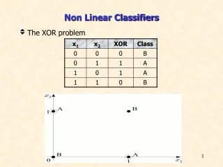
Outline of the talk • Case study of a reactive flash • Singularity theory, principles • Coupled Reactor Separator systems • Motivation for the study • Issues involved • Different control strategies for reactor/separator • Mass coupling, energy coupling • Effect of delay or transportation lag • Effect of an azeotrope in VLE • Operating reactor under fixed pressure drop • Conclusions
Reactive flash continued… • Model assumptions • nth order irreversible exothermic reaction • Reactor is modeled as a CSTR • CSTR is operated under boiling conditions • Dynamics of condenser neglected • Ideal VLE assumed
Model equations Where xA is the mole fraction of component Aα is ratio of activation energy of reaction to latent heat of vaporization And β is related to the difference in the boiling pointSteady state is governed by xAf,Da, α,βand n.
Multiple steady states in two-phase reactors under boiling conditions may occur if the order of self-inhibition α is greater than the order n of the concentration dependency of the reaction rate.
Physical cause of multiplicity • Here a phase equilibrium driven self inhibition action causes steady state multiplicity in the system • When the reactant is more volatile then the product, then a decrease in reactant concentration causes an increase in temperature. This causes further increase in reaction rate and hence results in a decrease in reactant concentration. • This autocatalytic effect mentioned just above causes steady state multiplicity
Singularity theory • Most models are non linear. The processes occurring in them are non linear • Non linear equations which are well understood are polynomials • Hence we try to identify a polynomial which is identical to the nonlinear system which models our process
Singularity theory can beused for • To determine maximum number of solutions • and to determine the different kinds of bifurcation diagrams , dependency of x on Da • and identify parameter values α,β where the different bifurcation diagrams occur
Singularity theory draws analogies between polynomials and non linear functions • Consider a cubic polynomial • It satisfies
Consider a non linear function • If the function satisfies • Then f has a maximum of three solutions
Singularity theory continued… • x i.e. the state variable of the system is dependent on Da. • The behavior of x Vs Da depends on the values of α and β. • Critical surfaces are identified in α-βplane across which the nature of bifurcation diagram changes.
Hysteresis variety • We solve for x, Da and α when other parameters are fixed
Isola variety • We solve for x, Da and α when other parameters are fixed
Motivation to study Coupled Reactor Separator systems • Individual reactors and separators have been analyzed • They exhibit steady-state multiplicity as well as sustained oscillations caused by a positive feedback or an autocatalytic effect • A typical plant consists of an upstream reactor coupled to a downstream separator • We want to understand how the behavior of the individual units gets modified by the coupling
Issues involved in modeling Coupled Reactor Separator systems • Degree of freedom analysis tells us how many variables have to be specified independently • The different choices give rise to different control strategies • Our focus is on behavior of system using idealized models to capture the essential interactions by including important physics • This helps us understand the interactions and enable us to generalize the results • This approach helps us gain analytical insight
Flow control strategies • Coupled Reactor separator networks can be operated with different flow control strategies • F0 is flow controlled and MRis fixed • F is flow controlled and MR is fixed • F0 and F are flow controlled.
Coupled Reactor Separator system“F0 is flow controlled and MRis fixed” The reactor is modeled as CSTR and separator as a Isothermal Isobaric flash The steady state behavior is described by
Steady state behavior of the coupled system • It can be established that the coupled Reactor Separator network behaves as a quadratic when F0 is flow controlled and MR is fixed. • So the system either admits two steady states or no steady state for different values of bifurcation parameters.
Coupled Reactor Separator network“F is flow controlled and MR is fixed” • The coupled system is described by the following equations • The steady state behavior is described by
Steady state behavior of the coupled system • It can be established that the coupled system behaves as a cubic • Qualitative behavior of the coupled system is similar to that of a stand-alone CSTR • This implies that the two units are essentially decoupled • Hysteresis variety and Isola variety can be calculated to divide the auxiliary parameter space
F0 and F are flow controlled • In this case coupled system is described by the following equations
Steady state behavior • It can be established that the system always possesses unique steady state when MR is allowed to vary and F0 ,F are flow controlled
F0 xaf V ye SEP F,z,T HX L,xe Mass and Energy coupled Reactor Separator network
Mass and Energy Coupled Reactor Separator Network • The coupled system in this case is described by
Steady state behavior of the system is described by It can be established analytically that system posses hysteresis variety at γ=0.5 when β=0 i.e. for adiabatic reactor
Delay in coupled reactor separator networks • Delays can arise in the coupled reactor separator networks as a result of transportation lag from the reactor to separator • Delay can induce new dynamic instabilities in the coupled system and introduce regions of stability in unstable regions
Model equations for Isothermal CSTR coupled with a Isothermal Isobaric flash F0 is flow controlled and MR is fixed F is flow controlled and MR is fixed
Linear stability analysis • when Fis flow controlled and MRis fixed, delay can induce dynamic instability • when F0 is flow controlled and MRis fixed, delay cannot induce dynamic instability • Analysis with coupled non isothermal reactor, isothermal-isobaric flash indicates that small delays can stabilize regions of dynamic instability and large delays can destabilize the coupled system further
Critical Delay contours for ‘F’ fixed Stable Unstable Unstable
Influence of azeotrope on the behavior of the coupled system • When the feed to the flash has an azeotrope in the VLE at the operating pressure of the flash then • the system admits two branches of solutions • Recycle of reactant lean stream can take place from the separator to the reactor • The coupled system admits multiple steady states even for endothermic reactions
Autocatalytic effect • Consider a perturbation where z increases • This causes L to decrease • This results in an increase in τ • The temperature decreases, lowering the reaction rate • This causes an accumulation of reactant amplifying the original perturbation in z
Dynamic behavior of coupled system • The coupled system shows autonomous oscillations even when the reactor coupled with the separator is operated adiabatically