Download
1 / 7
70 likes | 140 Views
CDR strategy for MBQ steering correctors and MBQ. 1. Comments and proposal for MBQ Steering correctors :.

E N D
CDR strategy for MBQ steering correctors and MBQ Michele Modena, CERN TE-MSC
1. Comments and proposal for MBQ Steering correctors : • We propose to mount in TEST LAB and CLEX Modules quadrupoleswithout steering correctors since we propose to not procure (for the moment at least) shorter MBQ if steering correction in CLEX (only 1 MBQ type1 will be present!) not really needed. • As concerning steering corrector prototypes, following: - the 11 March Meeting, - the gap increase, - the lengths revision, we need to check/revise the design and after that we intend to launch the manufacturing of a type1 and of a type4 corrector. I think that today these correctors are mainly needed to check their performance and their eventual impact on the stabilization, and this can be done also off line of the Test Modules. • As concerning CLIC Module layout for CDR, we propose to set the “nominal” lengths of the MBQ and Correctors in order that they fit in the TODAY available space. This layout could be "frozen" after the design check of the correctors. Following this and previous point the old "nominal" correction strengths are NOT for the moment guaranteed. • If/when the modules lengths eventually changed, we could revise and procure new MBQs with new lengths in order to test a complete set of MBQ with steering correctors in test modules program. Michele Modena, CERN TE-MSC
2. March 11 Meeting outcome • The solution of MBQ independent steering correctors seems the only available after investigation on the other possible solution (i.e. adding steering coils inside the MBQ). In fact this solution seems to not guarantee an adequate field quality for both the quadrupole and dipole corrections. • An “ad hoc” meeting took place on March 11. Main conclusion are the following: - Dipole correction (for beam steering) could potentially operate at 100 Hz. We will target this more stringent operation mode compare to the 50 Hz one. - Analysis on the BPM acquisition/processing/etc. times leads to a settling time for the corrector of 2 ms. -The most realistic operation mode (and the one less impacting on stability!) should be with a relative small correction between pulse; it was estimated n ≤ ± 25% of the full “nominal” correction range between sequential pulse; (“nominal” correction range: 4, 3, 2, and 1 mTm for Type4,3,2,1). • These values will be now taken to re-compute the steering correctors design in full transient operation mode. Michele Modena, CERN TE-MSC
3. Status on MBQ steering dipole correctors: -AVAILABLE space for the Steering Correctors in the Module layout : Expecially in order to be coherent inside the CDR layout, we consider the following space available TODAY: -We will check if these lengths are sufficient for the required corrections. (Note: for vacuum pipe needs, the dipole aperture is now increased of ~ 10%; this will have also an impact (reduction) on performances). • -If results will show that the correction needed is not guaranteed, the only solution seems to short the length of the MBQ (and eventually an earlier change from different MBQ type along the Linacs). Michele Modena, CERN TE-MSC
4. MBQ steering dipole layout for CDR: 344 305.1 mm 1844 1775.2 mm Baseline (CDR) layout of MBQs lengths (NOTE: they are shorter of the actual prototypes) Michele Modena, CERN TE-MSC
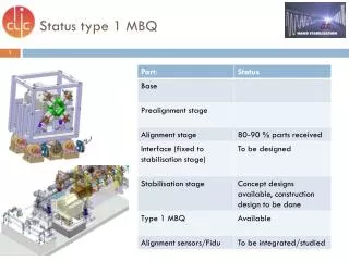
5. Status of Main Beam quadrupoles : -First set of coils and quadrants received since last year. -We have a serious contractual concern with the quadrants supplier (Heeze–NL) that has not fulfill the required tolerances, and not delivered the quality documentation. This situation should find an agreement but up to now we aren’t in the situation to freely dispose of all the quadrants. We have nevertheless decided to proceed now with the assembly of the 2 quads (type1 and type4) that will be soon urgent for stabilization studies. -All the ancillary pieces (ex. coils fixations and shimming materials to fix correctly the coils to the quadrants) are now procured and the assembly activities are starting today 28 March. -As soon as assemblies completed, we will proceed with functional tests, then with stabilization tests and magnetic measurements in a plan to be discuss in details with K. Artoos and M. Buzio. Activities are helped by the fact that we found a convenient area for assembly and tests (all types) in I8 (ISR Tunnel). Michele Modena, CERN TE-MSC
5. Status of Main Beam quadrupoles : Michele Modena, CERN TE-MSC