Download
1 / 25
250 likes | 380 Views
Modular Coil Assembly Fixture (MCAF). Information Meeting February 23, 2005. Agenda. Define the basic design requirements of the Modular Coil Assembly Fixture (MCAF), Define VV / MC clearances during MC assembly

E N D
Modular Coil Assembly Fixture(MCAF) Information Meeting February 23, 2005
Agenda • Define the basic design requirements of the Modular Coil Assembly Fixture (MCAF), • Define VV / MC clearances during MC assembly • Describe the Reference Design that was used to generate the MCAF design specifications, • Review the MCAF performance requirements as they currently stand, and • Answer questions
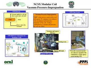
The design intent of the MCAF is pass two modular coil assemblies over the VV and accurately position mating flanges.
MC Design and VV Clearance Module Coil Half Period 1.76” actual minimum for nominal sizes
MC to VV Clearance A 1.76" (metal-to-metal) min clearance between MC’s and VV. MC is at its final position
MC to MC Clearance A 0.45” minimum clearance exists between wing region of Type A’s as the two half period MC shells comes together. Wing region
1.0” VV insulation 0.1875” VV tolerance 0.060” MC tolerance 1.25 ” Minimum Space How can assembly tolerances effect clearances? MC is at its final position 0.96”
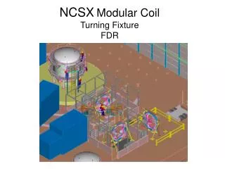
Gantry Crane Module Coil Half Period Turning Fixture / MC Interface Components Module Coil Half Period Type “C” Turning Fixture Type “A” Base Guide Rail VV Support Type “B” MCAF Reference Design The Reference Design was develop to qualify technical feasibility and help in establishing a design specification.
60 Deg 66.753” The relation between the Reference Design and Machine Coordinate System Machine Coordinate System Y Z X Y 6.125” Reference Design Coordinate System
. Y X Z For the Reference Design the X-axis was shifted up 6.125” Z Rz Rx X X Ry
The Reference Design MCAF motion is based on a 248 step servo table to drive six motors. MC is at its final position
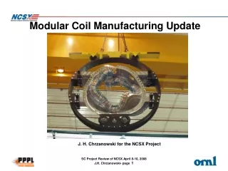
MCAF Component Details Module Coil Half Period (25000 lbs max) MCHP / Turning Fixture interface Pivot and rotation gimbal component (3200 lbs) Cradle component (6300 lbs) Vertical guide component (3500 lbs) 18,700 lbs (2700 lbs) Linear turntable structure Linear motion structure (3000 lbs)
Exploded isometric view MCHP / Turning Fixture interface Gimbal structure supports the MCHPand drives the pivot motion (“X rot”) A cradle structure support stabilizes and drives “Y rot” of a gimbal structure. The vertical guide component stabilizes four screw jacks (“Z” dir) which are driven by a single motor A linear turntable provides “X” motion with a pivot point (“Z rot”) and a bearing surface Base structure provides “Y” motion
RY = 13° RX = 5° DZ = 16” RZ = 15° DX = 12” Z Y X Extent of motion of turning fixture components. DY = 140”
MC Interface Structure A Local beam that interfaces with the gantry crane picks up existing MC holes Shaft attached to mid-section of Type “B” MC The MC CG location stays within the attachment points
Gantry crane designed with intermediate support system to provide final fit-up
In the final position two modular coil half periods will be separated by 0.50” (nominally) with three spherical seats engaged within an accuracy of 0.009”. . . If all goes well. Leica laser system used for assembly measurement.
What seismic design criteria do you apply during an assembly process? We have set a static seismic criteria of .108 as the design requirement following the NCSX Seismic Specification NCSX-CRIT-SEIS-00
Starting Position - CG Locations (Base End and Front Views) 18,300 MCHP 38,000 MCAF
Final Position - CG Locations (Front and Top Views from Base Structure) 18,300 MCHP 38,000 MCAF 100.0”
Side view show worst seismic position The existing base should work with captured rollers and a .108 static seismic factor but a broader base may be necessary if the CG moves up or a dynamic stop condition governs the design. 4104 lbs (assumes a .108 seismic factor) Capture roller 38,000 lbs 104” A 34”
Sideways clearances between MC shell and secondary support structure shall be greater that 60”
34.8’ 21.25’ Test cell assembly space requirements.
System Requirements • Performance Requirements • Fit-up and Assembly Space Allocation • Motion Controllers Requirements