Download

1 / 42
420 likes | 636 Views
Grand Challenge for Computer Science DARPA AGV Race 2005. Srini Vason srinivp@hotmail.com srini@datafluxsystems.com srini@eecs.berkeley.edu. Web Resources. Http://home.pacbell.net/srinivp www.datafluxsystems.com www.cyberrider.org www.darpa.mil/grandchallenge.

E N D
Grand Challenge forComputer ScienceDARPA AGV Race 2005 Srini Vason srinivp@hotmail.com srini@datafluxsystems.com srini@eecs.berkeley.edu
Web Resources • Http://home.pacbell.net/srinivp • www.datafluxsystems.com • www.cyberrider.org • www.darpa.mil/grandchallenge
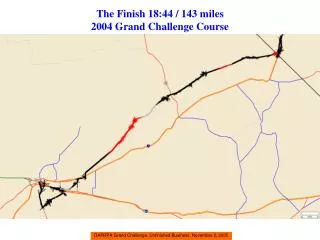
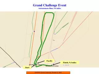
AGV Grand Challenge - Oct 8, 2005 • Traverse a distance of 200 miles through rough terrain from Barstow, CA to Los Vegas, NV in 10 hrs or less using an autonomous ground vehicle • No contact with the vehicle and a single failure in waypoint following results in disqualification • Route is given only two hours before the start of race • Best result so far is 7 miles by CMU in 20 min.
GC 2004 - March 13, 2004 • Waypoint file - spreadsheet • Video of waypoints created from aerial photographs and overlaying waypoints • Video of vehicles at the starting line (15 vehicles started) • Videos of cyberrider AGV under manual operation in the Barstow, CA OHA
Sensors and their Locations on Autonomous Ground Vehicle (AGV) Iri - Infrared sensor ODi - Odor and dust sensor Pi - Panorama cameras Ri - Radar Si - Ultrasound sensors (Sonar) Ti - Trinocular vision cameras WGHi - Water depth and ground hardness sensor WGH2 IR2 S2 S4 T2 P4 T4 T6 AGV OD1 T8 Back Front P1 T9 T10 P3 R2 R1 T7 OD2 T5 P2 T3 T1 IR1 WGH1 S1 S3
Real-time Integrated Sensors and GN&C Processing Road Models Database RDDF Video image streams Compass Data Image Stabilization Image to Road Model Correspondence Radar & Sonar Data streams Ladar Data GPS Error updates GPS Sensor Data & Map Data Path Planning & Path Tracking Stationary Obstacle Detection Moving Object Detection OD and WGH Sensors Data Wind & Env. Data Obstacle Tracking Other Vehicle Tracking Vehicle Sensors Data Run/pause/stop Steering, Brake, Cruise Control Correction Computation AGV Actuators Actuator Control Data Determination ESTOP
Waypoint list Driver Module Pause/run/stop Road model database Map Database Fusion Module Wheel encoders Ladar Vision Radar Digital compass GPS
AGV State Diagram E_pause Poweron Getset (start) Initialize Ready Start Diagnostics E_pause Cruise(run) Running/moving Boot_failure E_stop Ignition_on Fault Pause Cruise(run) E_stop Pause Stop Stopped Shutdown Powerdown
Challenges • Low-cost navigation sensors (GPS, vision, hardness detector, compass, ladar, radar, sonar) construction, calibration, and maintenance • Sensor processing in real-time (a few hundred TOPS) and stabilization of sensors • Synchronization of diverse sensor processing systems and hierarchical data fusion • Ambient (surrounding) awareness framework • Automatic steering, throttle, and brake control
Stop and go adaptive cruise control • Elimination of shadows fromvideo images in real-time after filtering, rectification, and LOG filtering • 3D Terrain profile construction from diverse sensors in real-time • Path finding between waypoints, path following, lane marker detection, and lane following • Perceptive passing • Stationary vegetation and solid obstacle detection on roads and trails • Moving object detection and collision avoidance
Pot hole, gutter, washboard, barbed wire, and fence post detection on trails • Scene analysis to adjust gazing angle for sensors • Cliff, canyon, switchback, and hill detection • Fault detection and recovery in real-time • AGV surviving in harsh environments ( rough roads, stream crossing, blowing wind and sand) • Experimental setup, testing, and measurement in harsh environments • Navigation during switchbacks, hill climbing, and descending
Road / Trail Following - cases • Path or trail following • Trail center line following • Road following (right side of road) • Road following with yellow divider line • Sharp turns in roads • Switchbacks in roads • Road following in rolling hills
Sensors and their Locations on the ROBOT IRi - Ladar/ Lasersensor Wi - wheel speed sensor T5, T6 - Edge detection cameras Ri - Radar Si - Ultrasound sensors (Sonar) T7 - Stereo vision cameras C3, C4 - Edge detection cameras DGPS – Differential GPS DC – Digital S2 Compass W2 C4 T6 ROBOT IR1 IR2 T7 Back Front R1 DC DGPS T5 C3 W1 S1
Experiments • Robots with sensors attached to them - DREAMbot • Campus level experiments using Robots
Sensors and their Locations on Autonomous Ground Vehicle (AGV) Iri - Infrared sensor ODi - Odor and dust sensor Pi - Panorama cameras Ri - Radar Si - Ultrasound sensors (Sonar) Ti - Trinocular vision cameras WGHi - Water depth and ground hardness sensor WGH2 IR2 S2 S4 T2 P4 T4 T6 AGV OD1 T8 Back Front P1 T9 T10 P3 R2 R1 T7 OD2 T5 P2 T3 T1 IR1 WGH1 S1 S3
Video Cameras • Low-cost camera array • Use it for edge detection • Use it for depth determination using stereo cameras • 3-D object recognition • 3D Terrain profile construction • Surrounding construction • Predictive passing
Cameras used in Edge Detection L-IBot camera R-IBot camera C-PtGrey camera Ladar Left camera Right camera Road coverage by Cameras Front View of Robot
Edge Detection - input/output • Edge detection is implemented in vision module. • The input to the edge detection is an image grabbed by the camera. • The color image (.ppm) is converted to a grayscale image (.pgm), and then the pgm image is processed with edge dection algorithm. • The output is a binary image in which 1 stands for places containing edge and 0 stands for places containing no edge or a packet containing edge vectors represented using end points. • The output image (compressed or vectorized) will be sent to Fusion module (cruise control node) in an UDP packet. • Unix program outputing UDP packets 10 times a second
Traversal Grid (0.75 m X 25 m) • Traversal grid is formed in front of the ROBOT for navigation. • The traversal grid is divided into an array of 160 rows and 12 columns at the bottom and 120 rows and 6 columns at the top • Each element in the lower part of the array represents a 6.25cm square. • Each element in the upper part of the array represents a 12.5cm square. • Each element in the array gets a 1 if an edge is found and a 0 if no edge is found in the binary image constructed from the compressed or vectored data given as output by an edge detection video camera.
75 cm 6 1 280 15m 25m 12.50cm X 12.50cm squares 161 160 10m 6.25cm X 6.25cm squares 1.25m 3 2 1 1 2 9 12
Navigation Scenario (waypoints outside trail) • The robot should pass through each way point and stay within the lateral boundary (LB) specified by the circle. • The waypoint may not be in the road and the robot should go along the road and stay within the LB area (which will be regarded as passing the way point). • Generally the road is straight between every two neighboring way points, but the robot should still not go off road. Robot’s path X road X X X
Some tips on using Intermediate points • Determine a road or trail near the two waypoints to be traversed. • If the map database contain intermediate points to traverse the waypoints, use them. • If no intermediate waypoints are found in the map database, follow the road and stay within the LB. Else traverse by staying within the LB (might have to go out of the road)
Navigation Algorithm usingRoad Edge Current heading 1.5m • The fusion module receives UDP packets from a vision node. • It decompresses the packets and reconstruct the binary edge image matrix. • Apply the traversal grid: • Select the partial matrix (pink rectangle) in the edge matrix based on the current heading . The partial matrix has double the width of traversal grid. • The inner matrix represents the traversal grid and has the same length as the partial matrix. It should be free of obstacles for the robot to move forward. • Check if there is an 1 in the inner matrix. If so, that means there is an obstacle in front and the robot needs to go around it by using steering control. 0.75m Inner matrix Partial matrix Image area 25m
Algorithm (contd.) • If there is a ‘1’ in the inner matrix but none in the rest of the partial matrix, rotate the inner matrix (left or right) enough to avoid the grid containing the ‘1’. This is an obstacle detection step to see if there is room for avoiding the obstacle. (Ignore points outside partial matrix when rotating) • If the inner matrix still resides in the partial matrix, robot will make a turn by the same angle we rotated the inner matrix. If not, slow the robot (for further detection and making new decisions). • If there is no ‘1’ in the inner matrix, proceed to go straight without making changes to steering angle. Current heading 1
Algorithm (contd.) • If an edge is detected in the partial matrix, the robot should make a slight turn to keep away from the edge. Current heading edge
Case discussion • The robot starts (WPT1) and goes forward to next way point (WPT2). • The vision module needs to look ahead (WPT3) to check the condition of the trail (or check the intermediate point to the current target way point). The look ahead allows the calculation of expected turning angle when reaching current target waypoint. This also gives a hint that the road will turn. • When the angle is calculated, the robot will be switched to one of the following cases: • The front is clear and the next way point is far away: go straight. • <1.7°: make a small correction to the direction. • 1.7°~5°: slow down and make a medium correction to the direction. • 5°~10°: slow down and prepare for turning in road. • 10°~20°: really slow and prepare for a sharp turn. • 20°~90°: stop and prepare for left and right turn. • Switch back in road:
Special situations - preprocessing • The edge detection algorithm should filter out small objects in the road by Wiener filtering the image. • If there is a big object in the road, the robot may first check if it is a road turn. It may check if there is an edge in the partial area or from any hints contained in the waypoints. • If this is a road turn, it will slow down and look at two sides to find the road. Otherwise, it should prepare to avoid the object.
Vision Module Design Steps(Edge Camera) • Acquire the image. • Pre process the image: filter small objects, shadows, and trail markings. • Apply edge detection scheme (Canny or Sobel) • Compress the binary image, packetize, and communicate to fusion module.
Vision Module Design Steps(Center Camera) • Acquire the image. • Enhance path edge. • Enhance center line. • Pre process the image: filter small objects, shadows, and trail marking (make sure that center line shows clearly.) • Apply edge detection scheme (Canny or Sobel) • Compress the binary image, packetize, and communicate to fusion module
Data Fusion using CMV • In the fusion module, we merge the data from different sensors by using the confidence measure vector (CMV) at each waypoint or intermediate point. • Initialize confidence measure vector. • Merge value for traversal grid. (edge detection, center line) • Follow center line. (center camera gets high confidence measure) • Follow path. (medium value for center camera and high value for edge detection)
Certainty Matrix (CM) • Points in the traversal grid are covered by different sensors. • The certainty of measurements at grid points change for each sensor. • Certainty matrix specifies how certain each measurement at the grid points are • Each sensor has a certainty matrix for the partial matrix • The value for certainty can be from 0 to 255 • Values 0 to 20 indicate low certainty and values 200 to 255 indicate high certainty on the measurements.
CM for T5 (left camera) • Camera’s sweet spot is between rows 11 and 100 • Rows 1 to 10 and cols. 1 to 6 : 150; cols. 7 to 12: 50 • Rows 11 to 100 and cols. 1 to 6: 200; cols. 7 to 12: 70 • Rows 101 to 130 and cols. 1 to6: 150; cols. 7 to 12: 50 • Rows 131 to 160 and cols. 1 to 6: 20; cols. 7 to 12: 20 • Rows 161 to 200 and cols. 1 to 6: 10; cols. 7 to 12: 0 • Rows 201 to 280 and cols. 1 to 6: 5; cols. 7 to 12: 0 • All rows and columns on the left side of column 1 in the partial matrix have the value 150
CM for T6 (right camera) • Camera’s sweet spot is between rows 11 and 100 • Rows 1 to 10 and cols. 1 to 6 : 50; cols. 7 to 12: 150 • Rows 11 to 100 and cols. 1 to 6: 70; cols. 7 to 12: 200 • Rows 101 to 130 and cols. 1 to6: 50; cols. 7 to 12: 150 • Rows 131 to 160 and cols. 1 to 6: 20; cols. 7 to 12: 20 • Rows 161 to 200 and cols. 1 to 6: 0; cols. 7 to 12: 10 • Rows 201 to 280 and cols. 1 to 6: 0; cols. 7 to 12: 5 • All rows and columns on the right side of column 12 in the partial matrix have the value 150
CM for T7 (center camera) • Camera’s sweet spot is between rows 11 and 100 • Stereo cameras allow depth map calculation also • Rows 1 to 10 and cols. 3 to 10 : 150; rest of the cols.: 50 • Rows 11 to 100 and cols. 3 to 10: 200; rest of cols. : 70 • Rows 101 to 130 and cols. 3 to 10: 150; rest of cols. : 50 • Rows 131 to 160 and cols. 3 to 10: 20; rest of cols. : 20 • Rows 161 to 200 and cols. 3 to 10: 10; rest of cols. : 0 • Rows 201 to 280 and cols. 3 to 6: 5; rest of cols. : 0 • All rows and columns on the left side of column 1 and right side of column 12 in the partial matrix have the value 0
Merging Data from Sensors • For each sensor use the CM to calculate values for each point in the traversal grid. • Form the data structure, MTA, merged_traversal_array(k, i, j) that contains for the kth sensor the value for the square on the ith row and jth column of the 0.75m X 25m traversal grid. The value can be 0 to 255. • Find the CMV for the current waypoint traversal by consulting the waypoint database and the threshold value (T). • Calculate the goodness measure for the traversal grid using the CMV. This calculation is shown as NMTA.
Normalized MTA (NMTA) • Let CMV = [v1 v2 v3 Vn], where n is the total number of sensors. • MTA[l, i, j] = vl * MTA[l, i, j] • NMTA[i, j] = (1/(255 *n)) * ( ΣMTA[l, i, j]) • Use threshold T on each element of NMTA to come up with a binary version of NMTA
Fusion Module Design (path following) (1) • Left camera gets camera data input: 1. Overlay camera axis. (XY for camera coordinate and X’Y’ for Robot coordinate) Y’ Y X (X’) Camera Robot Heading Heading Y Y’ X X’
Fusion Module Design (path following) (2) 2. Overlay path as determined by GPS coordinates. (Desired path) That is, given the current GPS coordinates and compass reading, locate the target waypoint position and calculate correct desired heading. Y Y’ Current heading Desired heading X X’
Fusion Module Design (path following) (3) 3. Overlay grid boundary. (inner matrix) 4. Overlay twice grid boundary. (partial matrix) Y Y’ Current heading Desired heading X X’
Fusion Module Design (path following) (4) 5. look for obstacles in grid. a. Ignore shadows , path marking (e.g. bikes, no bikes). b. Use Ladar data. c. Merge data. 6. Interference with road edge. Steering correction. 7. Turn. Slow the robot and then make the turn. Start path following again. 8. Repeat 1 to 7 for each sample. • This is useful when doing left turn. Y Y’ Current heading Desired heading X X’
Fusion Module Design (center line following) (1) • Input image comes from center camera after edge detection. • The center line is the path to be followed. • Overlay Grid on the image. • Look for interference between partial matrix and path edge. • Steering correction – line up with center line. Y X
Fusion Module Design (path following) (5) • Right camera: • Do the same sequence of steps as left camera. • This is useful in doing right turn.