Download
1 / 19
190 likes | 306 Views
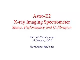
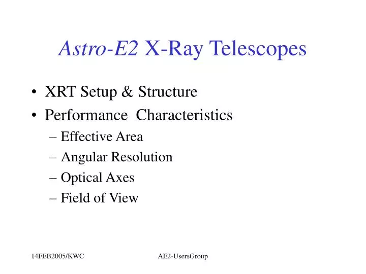
Astro-E2 X-Ray Telescopes. XRT Setup & Structure Performance Characteristics Effective Area Angular Resolution Optical Axes Field of View. XRT Set up. 5 XRT’s on extended bench 4 on imagers with f=4.75m 1 on spectrometer with f=4.50m Same external dimension for XRT-I & XRT-S

E N D
Astro-E2 X-Ray Telescopes • XRT Setup & Structure • Performance Characteristics • Effective Area • Angular Resolution • Optical Axes • Field of View AE2-UsersGroup
XRT Set up • 5 XRT’s on extended bench • 4 on imagers with f=4.75m • 1 on spectrometer with f=4.50m • Same external dimension for XRT-I & XRT-S • ~ 40 cm diameter, ~25 cm height AE2-UsersGroup
Structure • Optic • Reflective optics • Grazing incidence • Conical approximation to Wolter type I • 2 reflections in 2 stages • Collimation 1 stage • Gold surface • Nested shells of segmented “cylinder” Angle of incidence (on-axis) varies from inner (smaller) to outer (larger) spectral response: Critical angle ~ 1/E AE2-UsersGroup
Geometry and Mechanics • Segmented circular elements • Reflectors positioned in slots • (Almost) all constructed out of Al • Sandwiched elements: Gold surface / epoxy adhesion layer / aluminum substrate • Thermal properties • Operational T: 20 +/- 7.5 C • Sun shields • Heating elements • Thermal Shields Quadrant construction: 4- fold symmetry in image Sandwiched structure: dependence on temperature from CTE mismatch On ground, slight resolution dependence on orientation: displacement & gravity sag AE2-UsersGroup
Basic parameters of XRT AE2-UsersGroup
XRT Characterization from ISAS Measurements • ISAS pencil beam • Full illumination Data from JAXA/ISAS Y.Maeda ISAS 30 m pencil beam AE2-UsersGroup
Full XRT Images I0 I1 I2 I3 S AE2-UsersGroup
(Configuration) U X-ray W C D Effective Area ~ 9% down from E1 ~ 4% up from E1 Full Telescope Effective Area at 4.51 keV: XRT-I: I0-I3: 340 / 334 / 331 / 335 cm2 XRT-I average 335 cm2 XRT-S: 332 cm2 AE2-UsersGroup
Effective Areas • Rough numbers, for each XRT • ~ 450 cm2 at 1.5 keV • ~ 335 cm2 at 4.5 keV • ~ 245 cm2 at 8.0 keV (smaller ~ 90% for XRT-S at higher E) • ~ 175 cm2 at 9.4 keV • Au M edge at ~ 2 keV • Efficiency slight improved (a few %) from Astro-E1 • For XRT-S, difference is mainly due to Pt Au • Especially at higher energy due to larger critical angle of Pt AE2-UsersGroup
Angular Resolution Point Spread and Encircled Energy Functions AE2-UsersGroup
Angular Resolution: HPD AE2-UsersGroup
Angular Resolution • Measured with Half-Power Diameter from Encircled Energy Function • No dependence of angular resolution on energy • Indirect energy dependence on radial position of responsible reflectors • Errors in angular resolution (axial figure errors, positioning errors, etc.) are largely radius independent • HPD ~1.8’ • Focal length errors absorbed • Sharp core: inner r ~ 0.1’: sharply rising (~ linear) EEF ; no flat PSD (c.f. ASCA mirrors) • 90% encircled power within 4’ diameter AE2-UsersGroup
Focal Lengths & Orientation Dependence • Focal Length variation • as large as 50 mm • all errors due to focal length deviation are absorbed (measurement done at nominal f) • Dependence on orientation • Hope (optimistic) that resolution will be better in space: • no displacement • no gravity sag AE2-UsersGroup
Optical Axes AE2-UsersGroup
Optical Axis • Optical axes defined as the direction of maximum output • Not the bore sites (which are well sub-arc-minutes) • Optical axes of quadrants are located within +/-1 arcmin from the nominal telescope axes • Do not contribute to angular resolution (double reflection) • Lower throughput by <~5% at 1 arc minute AE2-UsersGroup
(Configuration) U X-ray Field of View Q3 W C D F.O.V. (FWHM) (XRT-I) 0’ 45’ 90’ Al-K 12 17 36 Ti-K 12 17 32 Cu-K 9 13 26 Pt-L 8 12 22 f (arcmin.) FOV of full XRT at 4.51 keV AE2-UsersGroup
Field of View • Collimator limits stray light, but not significantly restricts the aperture • Full XRT Field of View ~ 20’ at 4.5 keV • Energy dependence via radial dependence of responsible reflectors • Smaller FOV for higher energy x-ray (smaller critical angle of reflection) AE2-UsersGroup
Parameters for the Pre-collimator AE2-UsersGroup
Satellite Alignment AE2-UsersGroup