Download
1 / 183
1.83k likes | 2.29k Views
CICS (Customer Information Control System). Table of Contents. Introduction to CICS Basic Mapping Support Program Control File Processing Error Handling Queues Interval and Task Control Recovery and Restart Program preparation CICS Supplied Transactions Case Study.

E N D
Table of Contents • Introduction to CICS • Basic Mapping Support • Program Control • File Processing • Error Handling • Queues • Interval and Task Control • Recovery and Restart • Program preparation • CICS Supplied Transactions • Case Study
Introduction to CICS • Customer Information Control System -CICS developed in late 1960s as a DB/DC control system • CICS provides an interface between the Operating System and application programs • Macro Level CICS - initial version Assembler macro to request CICS services • Command Level CICS - high level lang.version - commands to request CICS services - Single command can replace series of macros
BATCH SYSTEM Input data is prepared and given in sequence (file) Processing sequence is predictable and hence restarting the process in case of failure is easy. Programs and files can’t be shared Programs are scheduled through jobs O/P printed on paper or in sequential of VSAM or Indexed files Response time: Could be scheduled to be Hours or days ONLINE SYSTEM Data is entered as needed not in sequence (terminal) Since processing sequence is unpredictable, special recovery/restart proc. is required in case of failure Programs and files can be shared Transaction can be run at any time O/p displayed on Terminal updated files Response Time: Could be in minutes or second. Usually in seconds Batch & Online : Differences
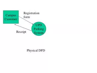
CICS & Operating System Operating System CICS Enter Code : User’s App. Files & Database
DB/DC System Terminals Data Base Central System CICS System Environment & API routines, and Application Programs
CICS System Services • Data-Communication Functions • Data-Handling Functions • Application Program Services • System Services • Monitoring Functions
Task & Transaction • Task :- A basic unit of work which is scheduled by the operating system or CICS Ex -Read from and write to the terminal • Transaction :- An entity which initiates execution of a task. In CICS, transaction is identified by the transaction identifier (Trans-id)
Application Programming Concepts • Pseudo-Conversational • Multitasking • Multithreading • Quasi-Reentrancy
Terminal Conversation • Conversational : A mode of dialogue between program and terminal based on a combination of sending message and receiving message within the same task • Since human response is slower than the CPU speed, a significant amount of resource will be wasted just waiting • Pseudo-Conversational. A mode of dialogue between program and terminal which appears to the operator as a continuous conversation but which is actually carried by a series of tasks
Terminal Conversation Example PROCEDURE DIVISION. : FIRST-PROCESS. EXEC CICS RECEIVE ---- <= TSK1,12345 END-EXEC. : process EXEC CICS SEND ----- <= EMP(12345) Details END-EXEC. * - - - - - - Program Waits For Response - - - - - SECOND PROCESS. EXEC CICS RECEIVE ----- <= User Enters Data END-EXEC. : process
Pseudo-Conversation Example Transaction TSK2 Program PROG2 PROCEDURE DIVISION. : EXEC CICS RECEIVE END-EXEC. : EXEC CICS SEND END-EXEC. EXEC CICS RETURN END-EXEC. Transaction TSK1 Program PROG1 PROCEDURE DIVISION. : EXEC CICS RECEIVE END-EXEC. : EXEC CICS SEND END-EXEC. EXEC CICS RETURN TRANSID (‘TSK2’) END-EXEC.
CICS Components • Control Programs (or Management Modules) Programs that interface between OS and app. pgm Handle the general functions that are crucial to operation of CICS • Control Tables Define the CICS environment Functionally associated with the management module • Control Blocks (or Areas) Contain system type information. Eg. Task Control Area contains information about the task
Mangement Pgms & Ctrl Tables • Programs Program Control PCP File control FCP Terminal Control TCP Task Control KCP Temporary Storage TSP Transient Data TDP Storage Control SCP Interval Control ICP Journal Control JCP • Tables • Processing Program • Table PPT • File Control Table FCT • Terminal Control Table TCT • Program Control Table PCT • Temp. Storage Table TST • Destin. Control Table DCT
CICS Program Considerations Considerations: • Must eventually return control to CICS • Can’t modify procedure division instructions because CICS programs may be shared by many tasks • Can modify working storage since a unique copy of working storage is created for each task
CICS Program Restrictions Restrictions: • No CONFIG. SECTION, I/O SECTION to be specified in the ENVIRONMENT DIVISION. • FILE SECTION, OPEN, CLOSE, and non-CICS READ & WRITE statements are not permitted because file management is handled by CICS. • COBOL commands such as ACCEPT, DISPLAY, EXHIBIT, TRACE, STOP RUN, GOBACK are avoided. (STOP RUN & GOBACK are sometimes included in order to eliminate compiler diagnostic but never executed)
Sample CICS Program IDENTIFICATION DIVISION. PROGRAM-ID. SAMPLE. ENVIRONMENT DIVISION. DATA DIVISION. WORKING-STORAGE SECTION. 01 WS-INPUT. 05 WS-TRANSID PIC X(4). 05 FILLER PIC X(1). 05 WS-IN-EMP-CD PIC X(4) VALUE ALL ‘X’.
Sample Program (Contd..) 01 WS-OUTPUT. 05 FILLER PIC X(16) VALUE ‘EMP CODE : ‘. 05 WS-OUT-EMP-CD PIC X(4). 01 WS-LENGTH PIC S9(4) COMP. LINKAGE SECTION. CAN Include DFHCOMMAREA if data needs to be communicated between two transactions or multiple iterations of the same transaction. PROCEDURE DIVISION. 000-MAINLINE. PERFORM 100-RECV-INPUT. PERFORM 200-SEND-OUTPUT. EXEC CICS RETURN END-EXEC.
Sample Program (Contd..) 100-RECV-INPUT. MOVE 9 TO WS-LENGTH. EXEC CICS RECEIVE INTO (WS-INPUT) LENGTH (WS-LENGTH) END-EXEC. MOVE WS-IN-EMP-CODE TO WS-OUT-EMP-CODE 200-SEND-OUTPUT. EXEC CICS SEND FROM (WS-OUTPUT) LENGTH (20) ERASE END-EXEC.
CICS Translator The CICS translator converts CICS commands into the COBOL code so that it could be compiled by a Standard Cobol compiler CICS Translator COBOL Statements CICS program with CICS Commands
Translator • When you compile a CICS/VS program the translator will automatically add many lines of code to your program, which can be seen in the compiled listing
Topics in BMS • Introduction to BMS • Map and Mapset • Physical and Symbolic Map • Map Definition Macros • Screen Manipulation/Handling • Screen Design Considerations • Interfacing with Terminal using a Map
Introduction to BMS Introductory concepts In online systems, formatted screens are used. In order to display formatted screen, a terminal (e.g. 3278) must receive a series of data stream called Native Mode Data Stream (NMDS) based on the hardware protocol;this NMDS is a mixture of Buffer Control Characters (BCCs) and text data. NMDS is designed for a particular terminal and is thus both device dependent and format dependent. So if NMDS is used, re-coding is required whenever there is change in the terminal device or screen format. To remove this device and format dependency from application program, CICS provides a facility called Basic Mapping Support (BMS).
Primary Functions of BMS • Removal of device dependent codes from Application Program • Removal of constant information from Application program (Headers, Titles...) • Construct NMDS - Native Mode Data Stream • Text handling • Terminal Paging & Message routing • Contents of the screen defined thru’ BMS is called Map. • Map is a program written in assembly language. • BMS macros are available for Map coding. The BMS Macros are coded in the form of Maps, and Mapsets to define the screen attributes, screen field positions, and field characteristics.
Map and Mapset • Representation of one screen format is called Map (screen panel). • One or more maps, link edited together, makes up a Mapset (load module). • Mapset must have a entry in PPT as given below: DFHPPT TYPE=ENTRY,MAPSET=name Or DFHPPT TYPE=ENTRY,PROGRAM=name
Map and Mapset (Contd..) • Mapset name has two parts. • Generic name 1- 7 chars. Used in App. Program. • Suffix 1 char. To identify the device type • Multimap Panel • Dynamically constructing a screen panel with multiple maps at the execution time
Map and Mapset (Contd..) The concepts of map and mapset can be utilized in two type of cases as given below: Case 1: A mapset consist of a single map. For e.g. MAPSET1 MAPNUM1 Case 2: A mapset consists of several maps. For e.g. MAPSET2 MAPNUM1 MAPNUM2
Types of MAPS There are 2 types of MAPS • Physical Map Physical Map is a map used by CICS (CSECT) Ensure device independence in the application program BMS macro coding ==> Assembly==> Link edit ==> Load module ==> LOADLIB ===> To be used by CICS • Symbolic Map Ensure device and format independence in the application program Symbolic Map is a map used by Application Program (DSECT) BMS macro coding ==> Assembly ==> Symbolic map definition ==> COPYLIB ==> Copied (COPY) into CICS application program.
Example – Symbolic Map 01 EMPRECI. 02 FILLER PIC X(12). 02 EMPNAL PIC S9(4) COMP. 02 EMPNAF PIC X. 02 FILLER REDEFINES EMPNAF. 03 EMPNAA PIC X. 02 EMPNAI PIC X(21). 01 EMPRECO REDEFINES EMPRECI. 02 FILLER PIC X(12). 02 FILLER PIC X(03). 02 EMPNAO PIC X(21).
Physical & Symbolic Map - Logic Flow BMS source Assembler Physical MAP Linkage editor Symbolic MAP Load module (MVS)
Physical Map Physical Map. • The BMS macros are assembled and link-edited into CICS load library to create the physical map. The mapset like any other CICS program is stored in CICS runtime library the PPT(Program Processing Table). At the program execution time the physical map is being used by CICS to load the screen image. • In case of input operations, the physical map defines the maximum length, the starting position for each field to be read and allows BMS to interpret an input NMDS. • In case of output operations, the physical map defines the starting position, length, field characteristics and the default data for each field and allows BMS to construct an output NMDS.
Symbolic Map • The symbolic map is coded using the BMS macro, assembled separately and catalogued into a copy library. The symbolic map serves as a DSECT for referencing the Terminal Input/Output Area (TIOA).The program issues a COBOL COPY statement to include it in the program. • The symbolic maps represents the actual data structure of the fields defined in the physical map, and is used by the application program to send and receive information from the terminal, in the CICS SEND-MAP & RECEIVE MAP commands. • The symbolic map can be used by the CICS application programs to dynamically to alter the field attributes, modify screen cursor position, and highlight , protect , unprotect specific fields on the screen.
Map definition Macros General Format Column Number 1 16 72 setname operation operands contd. Example EMPMAP DFHMSD TYPE=MAP, X MODE=INOUT, X LANG=COBOL, X STORAGE=AUTO, X TIOAPFX=YES * * ANY COMMENTS
Map definition Macros (Contd..) Explanations: SETNAME : Name of the mapset. Used in CICS command to read or write one of the maps in the mapset. It is the load module name. OPERATION : Macro identifier. Mapset/Map/Field definition. OPERANDS : Optional key words (parameters) separated by comma. CONTD : Current line can be continued by leaving this column non-blank (usually X) and the next line have to be started in 16th column. Comments : ‘*’ in column 1 makes the line comment.
Map definition Macros (Contd..) INITIAL VALUES : Always surround initial values by single quote marks Escape Chars : ‘ and &
Order of Macros DFHMSD TYPE=DSECT Mapset DFHMDI Map DFHMDF A field DFHMDF A field : DFHMDI Map DFHMDF A field DFHMDF A field : DFHMSD TYPE=FINAL Mapset END
DFHMSD Macro The DFHMSD macro is used to define a mapset (TYPE=MAP) and its characteristics or to end a mapset definition (TYPE=FINAL). Only one mapset is allowed in one assembly run. All the maps in a map set get assembled together, and they're loaded together at execution time. Example: TSTMSET DFHMSD TYPE=&SYSPARM, X MODE=INOUT, X LANG=COBOL, X STORAGE=AUTO, X TIOAPFX=YES, X CNTL=(FREEKB,FRSET,PRINT)
DFHMSD Macro (Contd..) Options TYPE= To define the map type DSECT For symbolic map MAP For physical map &SYSPARM For special assembly procedure FINAL To indicate the end of a mapset coding MODE= To indicate input/output operations IN For an input map only OUT For an output map only INOUT For maps involving both input and output.
DFHMSD Macro (Contd..) STORAGE = AUTO To acquire a separate symbolic map area for each mapset BASE To have the same storage base for the symbolic maps of from more than one mapset TIOAPFX= YES To reserve the prefix space (12 bytes) for BMS commands to access TIOA properly. Required for the CICS command level.
DFHMSD Macro (Contd..) CNTL= To define the device control requests FREEKB To unlock the keyboard FRSET To reset MDT to zero status ALARM To set an alarm at screen display time PRINT To indicate the mapset to be sent to the printer TERM=typeThis ensures device independence, required if other than 3270 terminal is being used SUFFIX=nn To specify the user provided suffix number. This must correspond to the TCT parameter.
DFHMDI Macro Defines a map and its characteristics Example EMPMAP DFHMDI SIZE=(ll,cc), X LINE=nn, X COLUMN=mm, X JUSTIFY=LEFT/RIGHT Options SIZE=(ll,cc)To define the size of the map by the line size (ll) and the column size (cc). Useful when the screen contains. LINEIndicates the starting line number of the map. COLUMNIndicates the starting column number of the map. JUSTIFYTo specify the entire map (map fields) is to be left or right justified.
DFHMDF Macro The DFHMDF macro is used to define a field in a map and its characteristics. This is the position on the screen where the field should appear. It's the position relative to the beginning of the map. Field starts with its attribute byte, so if POS=(1,1) is coded, then the attribute byte for that field is on line 1 in column 1, and the actual data starts in column 2. The length of the field (not counting the attribute byte) is specified. Literals can be specified within quotes; these character data is for an output field. It is used to define labels and titles for the screen and keep them independent of the program.
Sample Screen layout The above defines the screen layout as given below: Where ‘&’ Is the Attribute character ‘n’ Is unprotected numeric ‘_‘ Is Cursor ITEM NUMBER :&nnnnnnnn
DFHMDF Macro For The Above Layout Define a field and its characteristics Example DFHMDF POS(ll,cc), X INITIAL=‘Customer No. :’, X ATTRB=ASKIP, X LENGTH=14 CUSTNO DFHMDF POS=(ll,cc), X ATTRB=(UNPROT,NUM,FSET,IC), X JUSTIFY=RIGHT, X PICIN=‘9(8)’, X PICOUT=‘9(8)’, X LENGTH=8
Attribute character Function: The attribute character is an invisible 1-byte character, which precedes a screen field and determines the characteristics of a field. ASKIP Autoskip. Data cannot be entered in this field. The cursor skips to the next field. PROT Protected field. Data cannot be entered into this field. If data is entered, it will cause the input-inhibit status. UNPROT Unprotected field. Data can be entered and this is used for all input fields. NUM Numeric field. Only numbers (0 to 9) and special characters (“.” and “-“) are allowed.
Attribute character (Contd..) BRT Bright display of a field (highlight). NORM Normal display. DRK Dark display. IC Insert cursor. The cursor will be positioned in this field. In case, IC is specified more than once, the cursor is placed in the last field. FSET Field set. MDT is set on so that the field data is to be sent from the terminal to the host computer regardless of whether the field is actually modified by the user.
Modified Data Tag Function: Modified Data Tag (MDT) is a one bit of the attribute character. If it is off (0), it indicates that the terminal operator has not modified the field. If it is on (1), it indicates that the operator has modified this field. Only when MDT is on, the data of the field will be sent by the terminal hardware to the host computer. An effective use of MDT drastically reduces the amount of data traffic in the communication line and thus improves performance. Three ways of setting and resetting the MDT. 1. Terminal user modifies a field on the screen, it is automatically set to “1” (on) by the terminal hardware.
Modified Data Tag (Contd..) 2. If CNTL=FRSET is specified in the DFHMSD or DFHMDI macro, when the mapset or the map is sent to the terminal, MDT will be reset to “0” (off) i.e. not modified for all the fields of the mapset or the map. 3. If FSET is specified in the ATTRB parameter of the DFHMDF macro for a field, when the map is sent to the terminal, MDT will be set to “1”. (on i.e. modified) for the field regardless of whether the field has been modified by the terminal user.
Skipper Technique • Unlabelled 1-byte field with the autoskip attribute • DFHMDF POS(ll,cc),ATTRB=ASKIP,LENGTH=1 • To skip the cursor to the next unprotected field after one unprotected field. • Screen Layout : &xxxxx&$ &xx where $ Skipper field & Attribute byte X Unprotected field