Download
1 / 28
290 likes | 514 Views
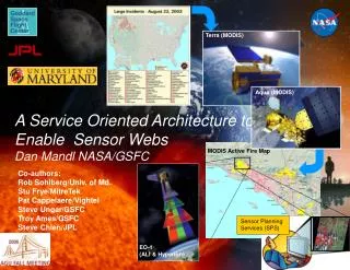
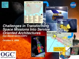
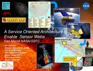
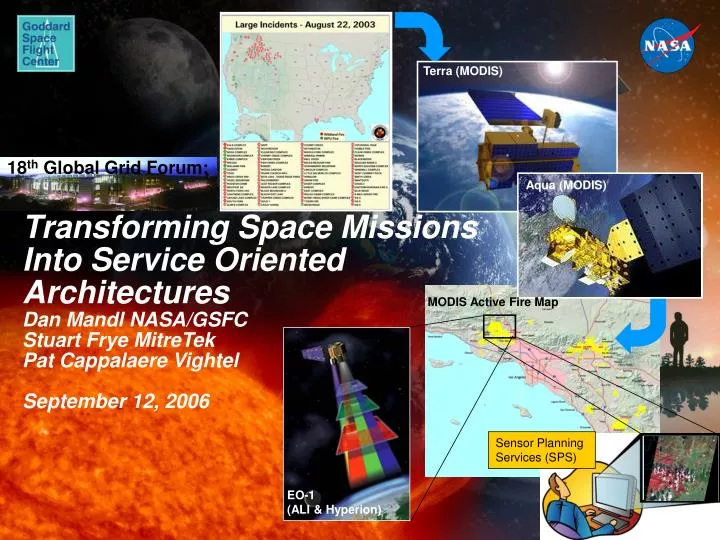
Terra (MODIS). 18 th Global Grid Forum:. Aqua (MODIS). Transforming Space Missions Into Service Oriented Architectures Dan Mandl NASA/GSFC Stuart Frye MitreTek Pat Cappalaere Vightel September 12, 2006. MODIS Active Fire Map. Sensor Planning Services (SPS). EO-1 (ALI & Hyperion).

E N D
Terra (MODIS) 18th Global Grid Forum: Aqua (MODIS) Transforming Space Missions Into Service Oriented ArchitecturesDan Mandl NASA/GSFCStuart Frye MitreTekPat Cappalaere VightelSeptember 12, 2006 MODIS Active Fire Map Sensor Planning Services (SPS) EO-1 (ALI & Hyperion)
Vision: Sensor Web Enablement via a Service Oriented Architecture (SOA) Scientists Sensor Planning Services (SPS) Land Remote Sensing Observation Data Sensor Alert Services (SAS) Sensor Registry Services (SRS) Sensor Observation Services (SOS) Work Flow Chaining Services (WfCS) Earth Weather Data • Abstract data from process of obtaining data via services above • Access sensors and data via Internet and use services similarly • to how “Google Earth” is used • User chains multiple services from various sensors and data • service providers together as needed • Built on top of GMSEC and cFE Space Weather Data
Service Example Back end “plug-ins” to fulfill service Front end of service “Generic request” Service Aggregator “I want a package delivered” UPS Deliver Package (DP) UPS FedEx FedEx Airborne Airborne Next Day $14.95 2 Day $7.95 Slow boat to China $1.25 • User discovers service on Internet with search tools • User picks desired service, pays and doesn’t get involved in • details of how service is provided • New services can be easily plugged in and removed thus • circumventing risk of obsolescence • Fault tolerant because user can locate and connect to alternative service
SPS Example: Discovering and Tasking EO-1 Sensors (OGC OWS-4 Demo) Front end of service “Generic request” Back end “plug-in” to fulfill service Service Aggregator SensorML Wrapper Sensor Planning Service (SPS) EO-1 Tasking Map CASPER Onboard Planner EO-1 SAS Internet EO-1 SPS • Wrap EO-1 satellite in • SensorML and publish • its capabilities • Enable generic command /tasking request via SPS • Enable generic alert • services via SAS ST5 SOS S/C ABC Auto-sync Future Expansion EO-1 Tasking Webserver Web Catalog Services ASPEN (Ground Planner) Database • Accept user goal requests • Automatically sort by priority • Perform auto-sync with onboard planner- CASPER • Store capabilities • Process user query and • return the result
SPS Example: Discovering and Tasking EO-1 Sensors (OGC OWS-4 Demo)
SPS Example Using ST5 Built on Top of GMSEC Front end of service “Generic request” Back end “plug-in” to fulfill service Service Aggregator GMSEC Bus Sensor Planning Service (SPS) Interoperable Message Bus Sensor Types Land Remote Earth Weather ST5 Planner SimulinkST5 Space Weather ST5 T&C Support Apps Matlab / Simulink Power ST5 SSR S/C XYZ RF Link Future RF SSR Power S/C ABC Future Expansion • Validated new “back-end” predictive models which predicted problems for selected subsystems (SSR, RF Link, Power)and then autonomously initiated corrective actions through planning system before problem occurred • - Unique innovation--Models self-update over time using real-time telemetry (e.g. as solar array degrades, charge current for battery changes over time, therefore model of state of battery has to change) • Used GSFC Mission Services Evolution Center (GMSEC) message bus to enable communications between support components
Example of Service Chain to Fulfill Science Data Processing Needs Sensor Observation Services (SOS) Sensor Alert Services (SAS) Sensor Planning Services (SPS) Sensor Registry Services (SRS) Subset raw data by band or time Work Flow Chaining Services (WfCS)—e.g BPEL Web Processing Service (WPS) WebMap Services (WMS) Web Feature Services (WFS) Process data and georectify- e.g.level1g, also Classify--Large!! Put on Map background Filter by feature, area, time (Discovery by feature) Web Coverage Service (WCS) Web browse image Find (Discover) sensors that can image wildfire Subset by geographic area or time of acquisition Smart Registry - eBRIM
Advantages of SOA for Space Sensors • Networked standardized interface connections, loosely coupled • Components connected at run-time • Enables discovery of services • Hides details of how service performed (encapsulated implementation) • Fault tolerant • Since connection occurs at run-time, if service not available, a component can find or “discover” an alternative service and if unavailable, can connect to another instance of the service if available • Troubleshooting is easier because information is provided at component and services level • Highly reusable • Standardized, networked “plug and play” interfaces • Scalable • Interactions between services and clients independent of location and numbers • Sustaining engineering for constellation simplified • Can initiate new instance of service or alternative service and then disconnect old services Taken from: Hartman, Hoebel; “Lightweight Service Architectures for Space Missions”, SMC-IT 2006, Pasadena, Ca
Key Capabilities Implemented to Enable EO-1 Sensor Webs & Support “Backend” of SPS
ASE Flight Software Architecture Raw Instrument Data Band Extraction ObservationPlanner Image ObservationGoals Overflight Times CASPER Planner – response in 10s of minutes Onboard Science High level S/C State Information Plans of Activities(high level) L2 – Model-based Mode Identification & Reconfiguration SCL – response in seconds with rules, scripts AutonomousSciencecraft Commands (low level) S/C State Conventional Systems EO 1 Conventional Flight Softwarereflexive response Control Signals (very low level) Sensor Telemetry Spacecraft Hardware
Original Operations Flow to Task Sensors & Access Science Data processed science data GSFC Science Processing USGS targets targets, engineering requests raw science data contacts Engineer White Sands weekly schedule station in-views Mission Planner FDSS overflights selected weekly schedule MOPSS tracking data daily activities CMS daily commands commands ASIST telemetry
Revised Operations Flow To Task Sensors and Access Science Data Using Onboard Autonomy processed science data JPL USGS GSFC targets, engineering requests Science Processing targets targets WWW SOA Users weekly goals raw science data targets White Sands contacts SPS ASPEN station in-views overflights daily goals Note that engineer and mission planner removed goals FDSS ASIST telemetry tracking data Onboard EO-1 science data Science Processing EO-1 goals commands CASPER SCL activities
Key Differences • Scenes and ground contacts are selected automatically based on scene priorities • World Wide Web interface for requesting and acquiring observations • High-level scene and contact “goals” are uploaded to the spacecraft instead of detailed command sequences • Execution sequence can be automatically changed on-board • Priority observations can be requested and acquired within hours • Science data is immediately available for analysis on-board compared to days or weeks
EROS Data Center Prototype Workflow Chain Service (WfCS) to Enable EO-1 Sensor Web to Targets National Priority Wildfires Fire location confirmed and selected for imaging 3 GSFC’s Science Goal Monitor 1 Identify NIFC-tracked Wildfire Incidents 3 SGM adds target to EO-1 ground & on-orbit planning & scheduling systems and tasks EO-1 1 Roberts Fire 2 4 SGM Correlate latest fire location information with MODIS imagery 5 L1 Data Roberts Fire UMD Natural Hazards Investigation Team 6 Active Fires Detection Map Aqua or Terra MODIS data Roberts Fire USFS Burned Area Emergency Response (BAER) team
Example of Rapid Delivery of Information for Decisions for EO-1 Sensor Web with WfCS On 11-2-03, the NASA Wildfire SensorWeb was employed to collect data on the burn scars resulting from the Simi Valley, Val Verde and Piru fires in Southern California. MODIS active fire detections for the duration of the event were used to target an acquisition by the ALI and Hyperion instruments onboard EO-1. Such data are employed by the USDA Forest Service for Burned Area Emergency Rehabilitation mapping. BAER maps are used to target high risk areas for erosion control treatments. MODIS Rapid Response Active Fire Detections In this image, burned areas appear red while the unburned areas appear green. The blue burn perimeter vector is based on ground data. EO-1 Advanced Land Imager Burn Scar Image
Integrated Flow forSensor Planning Service for EO-1: First Step Science Alerts Scientists Science Campaigns Science Agents Science Event Manager Processes alerts and Prioritizes response observations EO-1 Flight Dynamics Tracks, orbit, overflights, momentum management Observation Requests ASPEN Schedules observations on EO-1 Updates to onboard plan
Beginning to Implement Standards • GSFC Mission Systems Evolution Center (GMSEC) • Core Flight Executive (cFE) • Core Flight System (CFS) • SensorML • OGC Sensor Web Enablement (SWE) standards Satellites/ Sensors Ground Sensors Rovers Instruments Integrated Services Integrate Deploy Manage Create Application Services Others TBD Event Processing SensorML Archives Interoperability and Meta-Language Services IRC Others TBD SensorML Distributed Multi-Protocol Message Bus cFE For Space GMSEC For Ground
GMSEC Extended to S/C Bus--Onboard Integrated Message Bus Demonstration (December 2005) Ground System Testbed Core Flight Executive (cFE) on CHIPS DC ASIST Primary Command Ingest Telemetry Output UDP cFE Bus GMSEC Bus model Livingstone Adaptor ASIST Secondary script result DC – Data Center ASIST – Advanced Spacecraft Integration and System Test
Power Model Agent Adapter Power Model Agent Adapter Moving ST5 Models Onboard CHIPS Satellite Under cFS to Demonstrate Mobile Agents cFE Bus • Mobile agent –autonomous software module that can easily be moved around a network • Models transformed into mobile agents • Worked with Solid State Recorder agent (model) first • Adapter built to make compatible with both GMSEC and Core Flight Executive (cFE) • Demonstrated capability to move software running on GMSEC onboard to run under cFE • Demonstrates beginning step to transform missions from central control to distributed control via self-managing software CHIPS Satellite with cFE Bus Onboard Command Ingest Telemetry Output SSR Model Agent Adapter Goddard Space Flight Center ST-5 Constellation via Berkeley & Wallops Ground Stations (UDP) GMSEC Apps ASIST DC AMPS Fairmont, WV Demo App GMSEC Bus via DSN & McMurdo Ground Stations via TCP/IP CHIPS – Cosmic Hot Interstellar Plasma Spectrometer ST-5 – Space Technology 5 DC – Data Center ASIST – Advanced Spacecraft Integration and System Test
Extended Efforts • GMSEC to used on SDO, GLAST, LRO • GMSEC providing framework for C3I work in the Constellation Program • Will be used for ground and constellation of laboratories • Two recent follow-on 3 year awards from AIST ESTO call for proposal to extend ST5 efforts • An Inter-operable Sensor Architecture to Facilitate Sensor Webs in Pursuit of GEOSS • Key topic – Interoperability and demonstration of service oriented architecture for space missions and sensor webs • PI: Dan Mandl - 3 year effort • Using Intelligent Agents to Form a Sensor Web for Autonomous Mission Operations • Key topic distributed mission control • Extend effort depicted on slide 16 in which ST-5 components turned into mobile agents for use onboard spacecrafts with GMSEC/CFS • PI: Ken Witt/ISR Co-I Dan Mandl/GSFC – 3 year effort
Extended Efforts • Goddard Institute for Systems, Software and Technology Research (GISSTR) contract effort being applied to extend ST5 effort by Institute of Scientific Research (ISR) • Building GMSEC compliance tester for new components • Help to synergize other ESTO awards with above mentioned awards • Integrate ROME in collaboration with Capitol College into TRMM, GLAST and MMS • West Virginia Challenge Grant (set-aside) to be applied to develop Sensor Modeling Language (SensorML) schemas for follow-on SOA efforts • SensorML schemas will describe sensor capabilities and once put in online registries, will enable discovering of those capabilities on the Internet • Open Geospatial Consortium (OGC) ongoing testbed effort OGC Web Services 4 (OWS-4) June 2006- December 2006 • 200 member organization of OGC • 40 organization participating in OWS-4 • Sensor Planning Service (SPS) one of key services being demonstrated with EO-1
Acknowledgements • Additional info at: eo1.gsfc.nasa.gov and ase.jpl.nasa.gov • Other Team Members: • GSFC: Jerry Hengemihle, Scott Walling & Bruce Trout (Microtel), Jeff D’Agostino (Hammers), Seth Shulman (Operations Lead, Honeywell), Lawrence Ong (SSAI), Stephen Ungar (EO-1 Scientist), Thomas Brakke • JPL: Steve Chien (ASE PrincipaI Investigator), Rob Sherwood (ASE Experiment Mgr), Daniel Tran (Software Lead), Rebecca Castano (Onboard Science Lead), Ashley Davies (Science Lead), Gregg Rabideau, Ben Cichy, Nghia Tang • Interface & Control Systems (ICS): Darrell Boyer, Jim Van Gaasbeck • Univ. of Maryland: Rob Sohlberg (Wildfire Sensor Web) • Univ. of AZ: Victor Baker, Felipe Ip, James Dohm • ASU: Ronald Greeley, Thomas Doggett • MIT LL: Michael Griffin, Hsiao-hua Burke, Carolyn Upham
Acronyms • ASE – Autonomous Sciencecraft Experiment • ASIST – Advanced Spacecraft Integration and System Testing • ASPEN – Automated Scheduling Planning Environment • CASPER – Continuous Activity Scheduling Planning Execution and Replanning • CMS – Command Management Systems • MOPSS – Mission Operations Planning and Scheduling Systems • SCL - Spacecraft Command Language
Underlying “Plug and Play” Message Bus Architecture-- Goddard Mission Services Evolution Center (GMSEC) GMSEC architecture provides a scalable and extensible ground and flight system approach • Standardized messages formats • Plug-and-play components • Publish/Subscribe protocol • Platform transparency • ST5 first mission to be totally GMSEC compliant More info at: http://gmsec.gsfc.nasa.gov
Core Flight Executive (cFE), an Extension for GMSEC for Flight SW cFE provides a framework that simplifies the development and integration of applications • Layered Architecture – software of a layer can be changed without affecting the software of other layers • Components communicate over a standard message-oriented software bus, therefore, eliminating the need to know the details of the lower layers of inter-networking. • Software components can be developed and reused from mission to mission. • Developed by Flight SW Branch at GSFC • To be used on LRO • More info at: http://gmsec.gsfc.nasa.gov
Example of Rapid Mission Configuration Using GMSEC Interoperable Catalog Components GMSEC approach gives users choices for the components in their system. The TRMM mission rapidly selected key components from the GMSEC catalog.