Download
1 / 19
190 likes | 284 Views
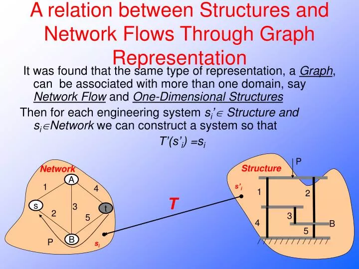
A relation between Structures and Network Flows Through Graph Representation. It was found that the same type of representation, a Graph , can be associated with more than one domain, say Network Flow and One-Dimensional Structures

E N D
A relation between Structures and Network Flows Through Graph Representation It was found that the same type of representation, a Graph, can be associated with more than one domain, say Network Flow and One-Dimensional Structures Then for each engineering system si’ Structure and siNetwork we can construct a system so that T’(s’i) =si P Structure Network A 1 s’i 4 1 2 T 3 s t 2 3 5 4 B 5 B P si
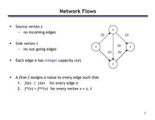
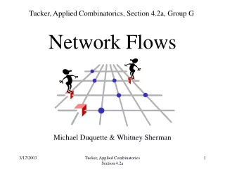
Network Flow and its connection to structures • The following slides will demonstrate the close relation between maximum flow in networks and applying a maximal force in a one dimensional structure.
One dimensional structures • In 1965, William Prager established the relation between network flow and plastic theory for one dimensional structures. • Prager used graph theory in order to establish the connection between the two seemingly different areas.
One dimensional structures • A one-dimensional structure is a solid structure built of rods and discs, where all rods are parallel to each other. P Disc Rods Ground
Network Flow and its connection to structures • The rules are pretty straight forward – each disc is replaced by a vertex and each rod by an edge. structurenetwork P A s 1 4 1 2 3 A t s 3 5 2 4 B 5 t B P
One dimensional structures • Applying more than the allowable force will in turn transform the structure into a mechanism. • Cable – A rod which preserves its length but cannot accept any compression (Recski) • Strut – A rod which cannot accept any tension P s A B t P s Energy preservation law: A B t
Network Flow - Example A 3 5 1 10 5 t s B
Network Flow - Example A One can see that the maximum flow is 9. 3 5 1 10 5 t s B
One dimensional structures- and its link to networks • Let’s assume now that we have the following one-dimensional structure: p s 3 10 A B 1 5 5 t
One dimensional structures- and its link to networks • Where the numbers refer to the maximal allowable force in each rod. p s 3 10 A B 1 5 5 t
One dimensional structures- and its link to networks • Now we have to find the maximal force that can be applied on the structure before any of its discs start moving. p s 3 10 A 1 B t 5 5
One dimensional structures- and its link to networks • Now, finding a cutset in the structure in which all rods are saturated means we have a mechanism: • The optimal solution here is 9, and one of the paths is marked in the graph: P Isomorphic s A 3 0 4 5 10 1 5 2 0 3 A 0 1 B 0 1 s t 5 0 1 5 2 t 5 4 5 0 10 Min Cut Max Flow Augmenting Path B
Network Flow and its connection to structures • What we get is the graph representation of the structure which is isomorphic to the network. • Now, finding the maximal allowable force is the same objective as finding the maximum allowable flow. structureNetwork p s 1 2 1 4 A 3 4 3 B 2 5 5 P t A t s B
A relation between Structures and Network Flows Through Graph Representation It was found that the same type of representation, a Graph, can be associated with more than one domain, say Network Flow and One-Dimensional Structures Then for each engineering system si’ Structure and siNetwork we can construct a system so that T’(s’i) =si P Structure Network A 1 s’i 4 1 2 T 3 s t 2 3 5 4 B 5 B P si
A relation between Structures and Linear Programming Through Matroid theory It was found that the same type of representation, a Matroid can be associated with more than one domain, say LP (Linear Programming) and Multi-Dimensional Structures Then for each engineering system siLP we can construct a system si’ Structures so that T(si)=mi =T’(s’i) LP Structures Max Matroid Q(M)*F=0 B(M)*D=0 T’ st T mi s’i si
The map of domains FGR Flow Graph Representation PGR Potential Graph Representation RGR Resistance Graph Representation LGR Line Graph Representation FLGR Flow Line Graph Representation PLGR Potential Line Graph Representation LP Linear Programming RMR Resistance Matroid Representation Frames Dynamical system Electronic circuits Static lever system Trusses Max st Q(M)*F=0 B(M)*D=0 Q(G)*F=0 B(G)*D=0 F=k*D Dual Dual Network Flow Operational research Serial robots Stewart platform Plane kinematical linkage Pillar system Determinate beams Planetary gear systems
Matroid Representation The scalar cutset matrix defines the matroid MQ=(S,F) where S is the set of columns of Q(G) and F is a family of all linearly independent subsets of S. S={1,2,3,P) 2 1 3 F={{1},{2},{3},{P},{1,2},{1,3},{1,P},{2,3},{2,P},{3,P}} P
Choosing a base Choosing augmenting path Choosing determinate structure t s Choosing a cut Removing these rods makes the structure not rigid Choosing a cut t s Choosing a set of linearly dependant members Choosing a cycle Choosing a self stress t s Flow law Q(M)*F=0 Force law The maximum values of the members The weights in the edges Allowable force in each rod
Choosing a base A group of manufacturing workers Choosing a set of linearly dependant members A group of manufacturing workers and an administrative/non-manufacturing worker Q(M)*F=0 The sum of hours that a worker manufactures the products equals to the sum of his Working hours B(M)*D=0 A unit’s cost equals to the sum of the hours multiplied by the workers’ wages P The maximum values of the members The workers’ hour constraint