Download

1 / 25
250 likes | 425 Views
Schenley Place Pittsburgh, PA. Final Thesis Presentation. Hali Voycik I Structural Option M. Kevin Parfitt, P.E., Thesis Advisor. PROJECT OVERVIEW. PRESENTATION OUTLINE Introduction Project Overview Scope of Work Structural Depth Study Building Site Relocation

E N D
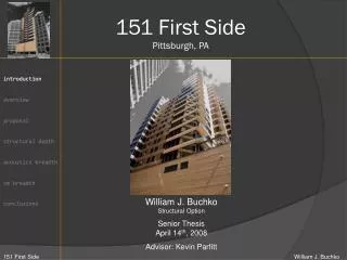
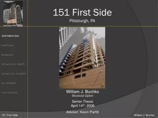
Schenley Place Pittsburgh, PA Final Thesis Presentation Hali Voycik I Structural Option M. Kevin Parfitt, P.E., Thesis Advisor
PROJECT OVERVIEW PRESENTATION OUTLINE Introduction Project Overview Scope of Work Structural Depth Study Building Site Relocation Existing Structure Gravity Framing for 3-story Addition Redesign of Supporting Gravity Systems Design of Lateral Force Resisting Systems Determination of Effective LFRS Architectural Breadth Evaluation of LFRS Relocation Construction Management Breadth Evaluation of Cost due to 3-story Addition Evaluation of Benefits to Owner Conclusions • Acknowledgements Questions BAYARD ST BUILDING LOCATION 4420 Bayard Street Pittsburgh, PA 15213 OCCUPANCY TYPE Typical office PROJECTED COST $17.5 Million SIZE 165,000 SF PROGRAM 7 levels of unfinished tenant space 3.5 levels of parking garage KEY PLAYERS Elmhurst Group, owner Burt Hill, architect Atlantic Engineering Services, structural BIGELOW BLVD N BELLEFIELD AVE BUILDING SITE RUSKIN ST Image courtesy of Google Map
PRESENTATION OUTLINE Introduction Project Overview Scope of Work Structural Depth Study Building Site Relocation Existing Structure Gravity Framing for 3-story Addition Redesign of Supporting Gravity Systems Design of Lateral Force Resisting Systems Determination of Effective LFRS Architectural Breadth Evaluation of LFRS Relocation Construction Management Breadth Evaluation of Cost due to 3-story Addition Evaluation of Benefits to Owner Conclusions • Acknowledgements Questions SCOPE OF WORK STRUCTURAL DEPTH STUDY Relocate Schenley Place Office Building to a site free of zoning and design constraints Design the gravity framing for a 3-story addition of rentable office space Redesign the supporting above and below grade gravity systems of the existing structure Design a lateral force resisting system that effectively reduces torsional effects ARCHITECTURAL BREADTH STUDY Evaluate the effect relocating the LFRS core has on the existing floor plans CONSTRUCTION MANAGEMENT BREADTH STUDY Evaluate the effect a 3-story addition has on the final cost of the existing structural system Determine if the owner benefits from a 3-story addition
BUILDING DESIGN PRESENTATION OUTLINE Introduction Project Overview Scope of Work Structural Depth Study Building Site Relocation Existing Structure Gravity Framing for 3-story Addition Redesign of Supporting Gravity Systems Design of Lateral Force Resisting Systems Determination of Effective LFRS Architectural Breadth Evaluation of LFRS Relocation Construction Management Breadth Evaluation of Cost due to 3-story Addition Evaluation of Benefits to Owner Conclusions • Acknowledgements Questions • Originally designed as a 10-story building • Final 7-story design and existing geometry dictated by historic zoning constraints governing the building’s site due proximity to: Schenley Farms—a historic residential district 2. The First Baptist Church of Pittsburgh—a designated historic structure SCHENLEY FARMS FIRST BAPTIST CHURCH BUILDING SITE Image courtesy of Google Map
HISTORIC PROTECTION ZONING ORDINANCES PRESENTATION OUTLINE Introduction Project Overview Scope of Work Structural Depth Study Building Site Relocation Existing Structure Gravity Framing for 3-story Addition Redesign of Supporting Gravity Systems Design of Lateral Force Resisting Systems Determination of Effective LFRS Architectural Breadth Evaluation of LFRS Relocation Construction Management Breadth Evaluation of Cost due to 3-story Addition Evaluation of Benefits to Owner Conclusions • Acknowledgements Questions Image courtesy ofGoogle Map Image courtesy of The Elmhurst Group
PRESENTATION OUTLINE Introduction Project Overview Scope of Work Structural Depth Study Building Site Relocation Existing Structure Gravity Framing for 3-story Addition Redesign of Supporting Gravity Systems Design of Lateral Force Resisting Systems Determination of Effective LFRS Architectural Breadth Evaluation of LFRS Relocation Construction Management Breadth Evaluation of Cost due to 3-story Addition Evaluation of Benefits to Owner Conclusions • Acknowledgements Questions BUILDING SITE RELOCATION CENTRE AVE PROPOSED SITE BAYARD ST N CRAIG ST N BELLEFIELD AVE N DITHRIDGE ST BAYARD ST EXISTING SITE Image courtesy of Google Map RUSKI
PRESENTATION OUTLINE Introduction Project Overview Scope of Work Structural Depth Study Building Site Relocation Existing Structure Gravity Framing for 3-story Addition Redesign of Supporting Gravity Systems Design of Lateral Force Resisting Systems Determination of Effective LFRS Architectural Breadth Evaluation of LFRS Relocation Construction Management Breadth Evaluation of Cost due to 3-story Addition Evaluation of Benefits to Owner Conclusions • Acknowledgements Questions EXISTING STRUCTURE FOUNDATION SYSTEM Concrete perimeter caisson wall Concrete drilled caissons Concrete grade beams PARKING GARAGE FLOOR SYSTEM 11” two-way flat slab with drop panels GRAVITY SYSTEM 30”X18” concrete columns 8” to 12” concrete walls TYPICAL OFFICES FLOOR SYSTEM 3 ½” n.w.c. slab 3”-20 G composite metal floor deck GRAVITY SYSTEM Composite steel W-shape beams Steel W-shape columns LATERAL SYSTEM Eccentrically braced frames Concentrically braced frames
PRESENTATION OUTLINE Introduction Project Overview Scope of Work Structural Depth Study Building Site Relocation Existing Structure Gravity Framing for 3-story Addition Redesign of Supporting Gravity Systems Design of Lateral Force Resisting Systems Determination of Effective LFRS Architectural Breadth Evaluation of LFRS Relocation Construction Management Breadth Evaluation of Cost due to 3-story Addition Evaluation of Benefits to Owner Conclusions • Acknowledgements Questions GRAVITY FRAMING FOR 3-STORY ADDITION
PRESENTATION OUTLINE Introduction Project Overview Scope of Work Structural Depth Study Building Site Relocation Existing Structure Gravity Framing for 3-story Addition Redesign of Supporting Gravity Systems Design of Lateral Force Resisting Systems Determination of Effective LFRS Architectural Breadth Evaluation of LFRS Relocation Construction Management Breadth Evaluation of Cost due to 3-story Addition Evaluation of Benefits to Owner Conclusions • Acknowledgements Questions REDESIGN OF SUPPORTING GRAVITY SYSTEM • ABOVE GRADE GRAVITY SYSTEM • RAM Steel Column used to optimize design • Wherever possible, original column depths maintained • BELOW GRADE GRAVITY SYSTEM • Existing designs analyzed in PCA Column • RAM Concrete Column Load Summary output used to verify designs • DRILLED CAISSION FOUNDATION SYSTEM • Designed with an end-bearing capacity of 25 tons per square foot
PRESENTATION OUTLINE Introduction Project Overview Scope of Work Structural Depth Study Building Site Relocation Existing Structure Gravity Framing for 3-story Addition Redesign of Supporting Gravity Systems Design of Lateral Force Resisting Systems Determination of Effective LFRS Architectural Breadth Evaluation of LFRS Relocation Construction Management Breadth Evaluation of Cost due to 3-story Addition Evaluation of Benefits to Owner Conclusions • Acknowledgements Questions ETABS MODELS • GENERAL ASSUMPTIONS AND CONSIDERATIONS • Only lateral members were modeled • Floor diaphragms were modeled as rigid area elements • Gravity loads were applied as additional area masses • BRACED FRAME ASSUMPTIONS AND CONSIDERATIONS • Column splices and beam-to-column connections were assumed rigid • Braces were released of end fixity • SHEAR WALL ASSUMPTIONS AND CONSIDERATIONS • Walls were modeled as area objects, meshed with maximum 48”X48” dimensions • Walls were modeled to only resist in-plane shear
PRESENTATION OUTLINE Introduction Project Overview Scope of Work Structural Depth Study Building Site Relocation Existing Structure Gravity Framing for 3-story Addition Redesign of Supporting Gravity Systems Design of Lateral Force Resisting Systems Determination of Effective LFRS Architectural Breadth Evaluation of LFRS Relocation Construction Management Breadth Evaluation of Cost due to 3-story Addition Evaluation of Benefits to Owner Conclusions • Acknowledgements Questions CONTROLLING LOAD CASES • DESIGN WIND LOADS • Design wind load cases were calculated by hand and applied manually • DESIGN SEISMIC LOADS • Design seismic load cases were calculated by hand and applied manually • Seismic accidental torsion was calculated by hand applied manually • Assumed inherent torsion was accounted for by ETABS
PRESENTATION OUTLINE Introduction Project Overview Scope of Work Structural Depth Study Building Site Relocation Existing Structure Gravity Framing for 3-story Addition Redesign of Supporting Gravity Systems Design of Lateral Force Resisting Systems Determination of Effective LFRS Architectural Breadth Evaluation of LFRS Relocation Construction Management Breadth Evaluation of Cost due to 3-story Addition Evaluation of Benefits to Owner Conclusions • Acknowledgements Questions DESIGN OF BRACED FRAME LFRS • DESIGN CONSIDERATIONS • Maintained design of a LFRS core as well as its existing location for practical reasons • Special attention paid to torsionaleffects
PRESENTATION OUTLINE Introduction Project Overview Scope of Work Structural Depth Study Building Site Relocation Existing Structure Gravity Framing for 3-story Addition Redesign of Supporting Gravity Systems Design of Lateral Force Resisting Systems Determination of Effective LFRS Architectural Breadth Evaluation of LFRS Relocation Construction Management Breadth Evaluation of Cost due to 3-story Addition Evaluation of Benefits to Owner Conclusions • Acknowledgements Questions FINAL DESIGN OF BRACED FRAME LFRS • FINAL DESIGN • Controlling wind design base shear: 448 kips • Design values determined via ETABS model and hand calculations • Designs of steel members verified through hand checks based on Specification for Structural Steel Buildings, 2005 (AISC 360-05) COLUMN LINE 5.1 COLUMN LINE 4 COLUMN LINE C COLUMN LINE D
PRESENTATION OUTLINE Introduction Project Overview Scope of Work Structural Depth Study Building Site Relocation Existing Structure Gravity Framing for 3-story Addition Redesign of Supporting Gravity Systems Design of Lateral Force Resisting Systems Determination of Effective LFRS Architectural Breadth Evaluation of LFRS Relocation Construction Management Breadth Evaluation of Cost due to 3-story Addition Evaluation of Benefits to Owner Conclusions • Acknowledgements Questions DESIGN OF SHEAR WALL LFRS • DESIGN CONSIDERATIONS • Maintained design of a LFRS core as well as its existing location for practical reasons • Accommodated existing architectural floor plans • Special attention paid to torsional effects
PRESENTATION OUTLINE Introduction Project Overview Scope of Work Structural Depth Study Building Site Relocation Existing Structure Gravity Framing for 3-story Addition Redesign of Supporting Gravity Systems Design of Lateral Force Resisting Systems Determination of Effective LFRS Architectural Breadth Evaluation of LFRS Relocation Construction Management Breadth Evaluation of Cost due to 3-story Addition Evaluation of Benefits to Owner Conclusions • Acknowledgements Questions FINAL DESIGN OF SHEAR WALL LFRS • FINAL DESIGN • Controlling wind design base shear: 448 kips • Design values determined via ETABS model and hand calculations • Steel reinforcement designed according to Building Code Requirements for Structural Concrete, 2008 (ACI 318-08)
PRESENTATION OUTLINE Introduction Project Overview Scope of Work Structural Depth Study Building Site Relocation Existing Structure Gravity Framing for 3-story Addition Redesign of Supporting Gravity Systems Design of Lateral Force Resisting Systems Determination of Effective LFRS Architectural Breadth Evaluation of LFRS Relocation Construction Management Breadth Evaluation of Cost due to 3-story Addition Evaluation of Benefits to Owner Conclusions • Acknowledgements Questions FINAL DESIGN OF SHEAR WALL LFRS • FINAL SHEAR WALL DESIGN • 18” thick walls • Designed both shear and flexural reinforcement • Uplift was accounted for in design of flexural reinforcement • Flexural reinforcement design was verified in PCA Column
PRESENTATION OUTLINE Introduction Project Overview Scope of Work Structural Depth Study Building Site Relocation Existing Structure Gravity Framing for 3-story Addition Redesign of Supporting Gravity Systems Design of Lateral Force Resisting Systems Determination of Effective LFRS Architectural Breadth Evaluation of LFRS Relocation Construction Management Breadth Evaluation of Cost due to 3-story Addition Evaluation of Benefits to Owner Conclusions • Acknowledgements Questions FINAL DESIGN OF SHEAR WALL LFRS • FINAL COUPLING BEAM DESIGN • 18” in width, 24” in depth (typical) • Designed both shear and flexural reinforcement • Not specially detailed for seismic
PRESENTATION OUTLINE Introduction Project Overview Scope of Work Structural Depth Study Building Site Relocation Existing Structure Gravity Framing for 3-story Addition Redesign of Supporting Gravity Systems Design of Lateral Force Resisting Systems Determination of Effective LFRS Architectural Breadth Evaluation of LFRS Relocation Construction Management Breadth Evaluation of Cost due to 3-story Addition Evaluation of Benefits to Owner Conclusions • Acknowledgements Questions DETERMINATION OF EFFECTIVE LFRS • DESIGN CONSIDERATIONS • System that adequately resists lateral loads • System that reduces the direct effects of torsion • Ftotal = Fdirect + Ftorsional • Where, Fdirect = Vikiand Ftorsional = kixi(Viey/Ji)
PRESENTATION OUTLINE Introduction Project Overview Scope of Work Structural Depth Study Building Site Relocation Existing Structure Gravity Framing for 3-story Addition Redesign of Supporting Gravity Systems Design of Lateral Force Resisting Systems Determination of Effective LFRS Architectural Breadth Evaluation of LFRS Relocation Construction Management Breadth Evaluation of Cost due to 3-story Addition Evaluation of Benefits to Owner Conclusions • Acknowledgements Questions ARCHITECTURAL BREADTH • EVALUATION OF LFRS RELOCATION • Feasibility initially assumed • Practical relocations of LFRS create greater eccentricities or interrupt exterior façade • Elimination of core and scattered lateral system interrupts open office floor plans
PRESENTATION OUTLINE Introduction Project Overview Scope of Work Structural Depth Study Building Site Relocation Existing Structure Gravity Framing for 3-story Addition Redesign of Supporting Gravity Systems Design of Lateral Force Resisting Systems Determination of Effective LFRS Architectural Breadth Evaluation of LFRS Relocation Construction Management Breadth Evaluation of Cost due to 3-story Addition Evaluation of Benefits to Owner Conclusions • Acknowledgements Questions CONSTRUCTION MANAGEMENT BREADTH • ASSUMPTIONS AND CONSIDERATIONS • Existing schedule and cost information was not attainable • Cost Works, a program created by RS Means used in analysis • Steel and area take-offs as computed by RAM
PRESENTATION OUTLINE Introduction Project Overview Scope of Work Structural Depth Study Building Site Relocation Existing Structure Gravity Framing for 3-story Addition Redesign of Supporting Gravity Systems Design of Lateral Force Resisting Systems Determination of Effective LFRS Architectural Breadth Evaluation of LFRS Relocation Construction Management Breadth Evaluation of Cost due to 3-story Addition Evaluation of Benefits to Owner Conclusions • Acknowledgements Questions CONSTRUCTION MANAGEMENT BREADTH IMPACT OF 3-STORY ADDITION ON COST OF STRUCTURAL SYSTEM TOTAL ADDITIONAL COST: $1,120,000
PRESENTATION OUTLINE Introduction Project Overview Scope of Work Structural Depth Study Building Site Relocation Existing Structure Gravity Framing for 3-story Addition Redesign of Supporting Gravity Systems Design of Lateral Force Resisting Systems Determination of Effective LFRS Architectural Breadth Evaluation of LFRS Relocation Construction Management Breadth Evaluation of Cost due to 3-story Addition Evaluation of Benefits to Owner Conclusions • Acknowledgements Questions CONSTRUCTION MANAGEMENT BREADTH BENEFIT OF 3-STORY ADDITION TO OWNER
PRESENTATION OUTLINE Introduction Project Overview Scope of Work Structural Depth Study Building Site Relocation Existing Structure Gravity Framing for 3-story Addition Redesign of Supporting Gravity Systems Design of Lateral Force Resisting Systems Determination of Effective LFRS Architectural Breadth Evaluation of LFRS Relocation Construction Management Breadth Evaluation of Cost due to 3-story Addition Evaluation of Benefits to Owner Conclusions Acknowledgements Questions CONCLUSIONS • A 3-story addition forces the redesign of the supporting above and below grade gravity systems • Redesign of drilled caisson foundation system is necessary • Braced frame lateral system determined most effective in reducing direct affects of torsion after comparative analysis of calculated torsional shears • The relocation of the LFRS core not structurally feasible • The design of a scattered LFRS is not architecturally feasible • Although the 3-story addition adversely impacts the final building cost, the owner benefits from the increased cost through increased profits allowing for a shorter pay-back period
PRESENTATION OUTLINE Introduction Project Overview Scope of Work Structural Depth Study Building Site Relocation Existing Structure Gravity Framing for 3-story Addition Redesign of Supporting Gravity Systems Design of Lateral Force Resisting Systems Determination of Effective LFRS Architectural Breadth Evaluation of LFRS Relocation Construction Management Breadth Evaluation of Cost due to 3-story Addition Evaluation of Benefits to Owner Conclusions Acknowledgements Questions ACKNOWLEDGEMENTS I would like to thank the following individuals and companies for the steadfast support they offered throughout the duration of the thesis process: The Elmhurst GroupAndy Gildersleeve Atlantic Engineering ServicesAndy Verrengia The Pennsylvania State UniversityThe entire AE Faculty Professor Parfitt And lastly, my family and friends for their unconditional support and encouragement.
PRESENTATION OUTLINE Introduction Project Overview Scope of Work Structural Depth Study Building Site Relocation Existing Structure Gravity Framing for 3-story Addition Redesign of Supporting Gravity Systems Design of Lateral Force Resisting Systems Determination of Effective LFRS Architectural Breadth Evaluation of LFRS Relocation Construction Management Breadth Evaluation of Cost due to 3-story Addition Evaluation of Benefits to Owner Conclusions Acknowledgements Questions QUESTIONS?