Download
1 / 1
10 likes | 92 Views
Instrumented Wheel for Wheelchair Propulsion Assessment Jacob Connelly, Andrew Cramer, John Labiak, Paul King, Ph D., Mark Richter, Ph.D. Vanderbilt University Department of Biomedical Engineering, Nashville, TN, USA Max Mobility LLC, Nashville, TN, USA. INTRODUCTION. PROTOTYPE II.

E N D
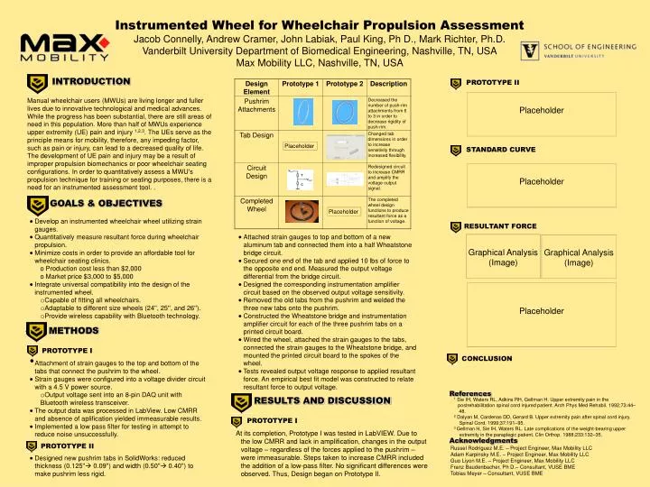
Instrumented Wheel for Wheelchair Propulsion Assessment Jacob Connelly, Andrew Cramer, John Labiak, Paul King, Ph D., Mark Richter, Ph.D. Vanderbilt University Department of Biomedical Engineering, Nashville, TN, USA Max Mobility LLC, Nashville, TN, USA INTRODUCTION PROTOTYPE II Placeholder Manual wheelchair users (MWUs) are living longer and fuller lives due to innovative technological and medical advances. While the progress has been substantial, there are still areas of need in this population. More than half of MWUs experience upper extremity (UE) pain and injury 1,2,3. The UEs serve as the principle means for mobility, therefore, any impeding factor, such as pain or injury, can lead to a decreased quality of life. The development of UE pain and injury may be a result of improper propulsion biomechanics or poor wheelchair seating configurations. In order to quantitatively assess a MWU's propulsion technique for training or seating purposes, there is a need for an instrumented assessment tool. . Placeholder STANDARD CURVE Placeholder GOALS & OBJECTIVES Placeholder • Develop an instrumented wheelchair wheel utilizing strain gauges. • Quantitatively measure resultant force during wheelchair propulsion. • Minimize costs in order to provide an affordable tool for wheelchair seating clinics. • Production cost less than $2,000 • Market price $3,000 to $5,000 • Integrate universal compatibility into the design of the instrumented wheel. • Capable of fitting all wheelchairs. • Adaptable to different size wheels (24'', 25'', and 26''). • Provide wireless capability with Bluetooth technology. RESULTANT FORCE • Attached strain gauges to top and bottom of a new aluminum tab and connected them into a half Wheatstone bridge circuit. • Secured one end of the tab and applied 10 lbs of force to the opposite end end. Measured the output voltage differential from the bridge circuit. • Designed the corresponding instrumentation amplifier circuit based on the observed output voltage sensitivity. • Removed the old tabs from the pushrim and welded the three new tabs onto the pushrim. • Constructed the Wheatstone bridge and instrumentation amplifier circuit for each of the three pushrim tabs on a printed circuit board. • Wired the wheel, attached the strain gauges to the tabs, connected the strain gauges to the Wheatstone bridge, and mounted the printed circuit board to the spokes of the wheel. • Tests revealed output voltage response to applied resultant force. An empirical best fit model was constructed to relate resultant force to output voltage. Graphical Analysis (Image) Graphical Analysis (Image) Placeholder . METHODS PROTOTYPE I • Attachment of strain gauges to the top and bottom of the tabs that connect the pushrim to the wheel. • Strain gauges were configured into a voltage divider circuit with a 4.5 V power source. • Output voltage sent into an 8-pin DAQ unit with Bluetooth wireless transceiver. • The output data was processed in LabView. Low CMRR and absence of aplification yielded immeasurable results. • Implemented a low pass filter for testing in attempt to reduce noise unsuccessfully. • Designed new pushrim tabs in SolidWorks: reduced thickness (0.125'' 0.09'') and width (0.50'' 0.40'') to make pushrim less rigid. CONCLUSION References RESULTS AND DISCUSSION 1 Sie IH, Waters RL, Adkins RH, Gellman H. Upper extremity pain in the postrehabilitation spinal cord injured patient. Arch Phys Med Rehabil. 1992;73:44–48. 2 Dalyan M, Cardenas DD, Gerard B. Upper extremity pain after spinal cord injury. Spinal Cord. 1999;37:191–95. 3 Gellman H, Sie IH, Waters RL. Late complications of the weight-bearing upper extremity in the paraplegic patient. Clin Orthop. 1988;233:132–35. PROTOTYPE I At its completion, Prototype I was tested in LabVIEW. Due to the low CMRR and lack in amplification, changes in the output voltage – regardless of the forces applied to the pushrim – were immeasurable. Steps taken to increase CMRR included the addition of a low-pass filter. No significant differences were observed. Thus, Design began on Prototype II. Acknowledgments PROTOTYPE II Russel Rodriguez M.E. – Project Engineer, Max Mobility LLC Adam Karpinsky M.E. – Project Engineer, Max Mobility LLC Guo Liyon M.E. – Project Engineer, Max Mobility LLC Franz Baudenbacher, Ph D.– Consultant, VUSE BME Tobias Meyer – Consultant, VUSE BME T C