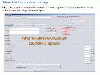
Download
1 / 101
1.04k likes | 1.18k Views
CDMA System Training. 9:00 Basics (for non-technical or “new” engineers) 10:00 Layers 2 & 3 12:00 Lunch 1:00 Physical Layer 3:00 Test Specification 4:00 Wrap-up. Agenda. CDMA System Training. User2. User3. User4. User1. User1. Time slot. time. USER1. USER2. USER3. USER4. time.

E N D
9:00 Basics (for non-technical or “new” engineers) 10:00 Layers 2 & 3 12:00 Lunch 1:00 Physical Layer 3:00 Test Specification 4:00 Wrap-up Agenda CDMA System Training
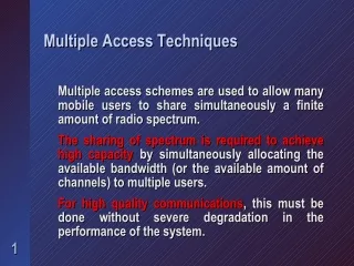
User2 User3 User4 User1 User1 Time slot time USER1 USER2 USER3 USER4 time Overview Multiple Access Terminology CDMA System Training • FDMA - Frequency Division Multiple Access • Different frequencies (channels) • TDMA - Time Division Multiple Access • Given a “time slot” • Same frequency as other users • CDMA - Code Division Multiple Access • Given a code or address • Codes are arranged not to interfere with each other • Same frequency as other users
Analog AMPS (IS-3) - Advanced Mobile Phone Service FM modulation with 30 kHz channels NMT - Europe TACS – British Digital CDMA2000/EVDO 1.25MHz, 1.2288MHz chip rate IS-136 – TDMA 30kHz WCDMA 5MHz, 3.84MHz chip rate TD-SCDMA 1.6MHz Overview Standards Around the World CDMA System Training
Overview What is a Cellular Phone? CDMA System Training • Two-way radio • Communicates with a another radio called a base station. • Base stations are connected together by telephone switches. • What is Radio Frequency (RF)? • Radio waves at a particular frequency or set of frequencies • RF provides a way of sending all types of information at the same time at different frequencies • Modulation of a carrier • Signal of interest is “put on” a carrier • Demodulation of a signal • Strips off the carrier to recover the original signal
What is the difference between cellular and PCS? Frequency band Cellular is at 800 MHz PCS is at 1900 MHz Transceiver (transmitter / receiver) Full duplex Transmitter sends at the same time it is receiving Separated in frequency Half duplex Take turns transmitting and receiving - not simultaneous Still usually separated by frequency. Overview Cellular Technology CDMA System Training PCS Cell
Overview System Determination and Registration CDMA System Training • Mobile looks for a system • Based on home SID / NID and channel number(s) • If the home SID is not found, phone then finds other systems • Roaming • Registration tells the system I am out here listening • Mobile monitors the channel for pages from the base station.
Overview How Does a Cellular Phone Make a Call? CDMA System Training • User presses keys to dial number • ASIC detects key press and interrupts MCU. • MCU reads the key pad word from the ASIC • User presses send - call origination • Information is sent to the base station over the air using a control channel. • For CDMA - Access Channel • Base station sends channel assignment message to mobile • For CDMA - Paging Channel / Traffic Channel • Voice is now heard on either side • For CDMA - Forward Traffic Channel and Reverse Traffic Channel
Overview How Does a Cellular Phone Make a Call (2)? CDMA System Training • For Call Termination (someone is calling the mobile) • Phone monitors for pages • For CDMA - Paging Channel • Phone responds to page • For CDMA - Access Channel • Base Station sends channel assignment message and everything proceeds as in origination.
Overview Mobile to Mobile Call CDMA System Training Base Station • Your voice is picked up by a microphone in the mobile phone and is modulated to Radio Frequencies (RF). • Digital phone digitizes voice and encodes it digitally. • The RF signal is transmitted to the closest Base Station. • The Base Station demodulates the signal. • The Base Station sends the data to a Mobile Switching Center (MSC) through digital wire line called a T1 line. • The MSC then sends the voice signal to the receiving MSC through the Public Switch Telephone Network (PSTN) digital trunk. T1 Mobile Switching Center
Overview Mobile to Mobile Call (2) CDMA System Training Base Station • The receiving MSC sends the signal to the closest Base Station to the other mobile via a T1 line. • The Base Station then modulates the signal on a different RF frequency. • The mobile phone demodulates the signal to the original voice signal and it is heard on the earpiece. T1 Mobile Switching Center
Overview Mobile to Landline Call CDMA System Training Base Station • Reception of voice by the base station is the same as previous. • The MSC then sends the data to the receiving PSTN switch through a digital trunk. • The receiving PSTN switch converts the digital signal to an analog voice signal to the landline phone receiving the call. • The analog signal is sent over standard telephone lines to the landline phone. • You hear the voice on the receiver earpiece. T1 Mobile Switching Center
Overview Why Digital? CDMA System Training Analog Signals: • ‘real’ • exact • continuous • sensitive to noise • voice only Digital Data: • symbolic • discrete • error protection • data capable • Data security • ideal hardware functions • low power processing • correction of errors by coding. • Results in clearer voice Digital Data is limited by the number of bits
Base Station RF Power Mobile RF Power Overview Handoff CDMA System Training • An RF signal get smaller and smaller (known as attenuation) as you move farther and farther away from the transmitter. • As the RF signal gets attenuated (that is, the mobile gets farther from the Base Station), the mobile must increase it’s RF output power. • As a mobile moves through the network and because of signal attenuation, the call must be “handed off” to another Base Station (also known as a cell site). • If a call was not handed off, the signal being received would get so small it could not be received and the call would be dropped.
CDMA System Training Overview Cells and Handoff This can be a picture or a table
CDMA System Training Overview Cells and Handoff (2)
CDMA System Training Overview Cells and Handoff (3)
CDMA System Training L2 / L3 Higher Layers - 2 and 3
L2 / L3 CDMA System - General CDMA System Training • CDMA is an interference limited system, which is why there is “soft” capacity. The capacity can be increased by degrading the quality of service, i.e., higher Frame Error Rate (FER). • CDMA is a multi-rate DS-CDMA (Direct Sequence). Chip rate = 1.2288 MHz. • The “overhead + user data” is the rate specified. • Rate Set 1 : 9600, 4800, 2400, and 1200 bits/second • Rate Set 2 : 14400, 7200, 3600, and 1800 bits/second • Traffic and paging data is broken up into 20 ms frames (50 Hz). • CDMA is spread with a super-orthogonal code (Walsh) of length 4,8,16,32,64,128. • Cross correlation is zero.
L2 / L3 CDMA System – General (2) CDMA System Training • Walsh chips are randomized by two Pseudorandom Noise (PN) sequences (I and Q) running at the chip rate. • Looks like white noise ! • I/Q PN is also referred to as the short code. • Repeat every 26.667 ms (32768 chips) • Base Stations (BS) are all synchronized in time to GPS time which is converted into CDMA system time. • System time is the combination of the long code (2**42 - 1) and the short code (2**15), which repeats every 37 centuries. • BS are separated in PN space by 64 chips known as BS offsets or pilots. In practice, neighboring cells are 12 BS offsets away (12*64 chips).
L2 / L3 CDMA System Features CDMA System Training • System capacity is reverse link limited because of non-coherence. • Fast power control of the reverse link helps capacity by limiting noise in the system. • Forward link control is way to slow and too long of a delay. • Typical capacity for voice calls • 20 users/carrier/sector for RS 1 • 13-14 users/carrier/sector for RS 2 • Carriers like “soft capacity” of CDMA. • Degrade the quality of all users on a carrier by lowering the power and gaining more capacity. • Frequency reuse is 1.0 (actual is 1.6)
Standards CellPCS IS-95 Prev 1 JSTD-008 IS-95A Prev 2 TSB-74 Prev 3 IS95B Phase 1 Prev 4 Phase 2 Prev 5 IS-2000 Rev 0 Prev 6 IS-2000 Rev 0 IS-2000 Rev A Prev 7 IS-2000 Rev A IS-2000 Rev B Prev 8 IS-2000 Rev B IS-2000 Rev C Prev 9 IS-2000 Rev C IS-2000 Rev D Prev 10 IS-2000 Rev D L2 / L3 Revision Numbers CDMA System Training
L2 / L3 Layer Overview CDMA System Training • L1 and LM are the lowest level software • L1 is physical layer control, such as tuning the RF, etc. • Strips out control data from traffic data from each frame. • Voice data goes to Vocoder SW. • Assembles frames with control and traffic for transmission based on rate of traffic data, e.g., voice. • Layer 2 • Responsible for reliability of signaling messages • ACK sequences, message sequences and message CRC. • Layer 3 • High level message handling • All messaging between MS and BS • Retransmission and duplicate messages • State transitioning
L2 / L3 MCU and DSP CDMA System Training • MCU and DSP processing is independent of layers. • DSP is responsible for time critical functions such as Vocoder. • MCU handles messaging and any non-time critical processing of L1, such as programming the RF synthesizers.
L2 / L3 CDMA Frames CDMA System Training • Frames are to divide up the data into small enough pieces to minimize delay and check validity of the contents. • Frame Quality Indicator (FQI) is a CRC check. • ‘0’ tail bits are added to clear the convolutional encoder (traffic) • Frame content information is add to the frame. • Traffic and paging channel frames • 20 ms in length • Convenient size for most voice applications (time delay critical) • Sync channel frame are based on PN repetition rate (26.667 ms) because that is all you know at the time. Sync channel 26.667 ms * 3 = 80 ms (superframe) Traffic / paging 20 ms * 4 = 80 ms Time alignment of 80 ms
L2 / L3 Service Options CDMA System Training • Service option is what is in the primary and/or secondary data • SO1 - 8 kbit vocoder (Qualcomm) • SO2 - 8 kbit loopback • SO3 - 8 kbit EVRC • SO9 - 13 kbit loopback • SO32768 & SO17 - 13 kbit vocoder (Qualcomm) • Service option number are defined in IS-58 • Service option negotiation takes place both before and after traffic channel assignment. ½ rate 13k voice ½ rate Signal-ing Full rate 13k voice 1/4 rate 13k voice 1/8 rate 13k voice Full rate signaling 20 ms traffic channel frames
L2 / L3 System Determination CDMA System Training • Based on channels and SID/NID • For systems with multiple channels (overlay) • Directed to a frequency via sync channel • Global Service Redirection • Hashing algorithm may be used • Mobile determines which frequency based on MIN • Spreads load more evenly over frequencies, paging channels, slots and accesses. • Idle handoff to another frequency • Stronger pilot found • Extended Neighbor List Message RX2 RX3 RX1
L2 / L3 Pilot Categorization CDMA System Training • Pilots (base station offsets) are divided into categories • Active set - pilot that have been approved to be used for demodulation • Candidate set - have exceeded the T_ADD threshold and are to be reported to the base station as potential pilots. • Neighbor set - pilots to be monitored by the mobile to see if they can be put in the candidate set. • Remaining set - all other pilots.
L2 / L3 Pilots and Handoff CDMA System Training • “Set Maintenance” is responsible for searching all sets with a particular period for each set. • Pilots in the active set that drop below T_DROP threshold are reported to the base station in Pilot Strength Measurement Message (PSMM). • Base station will most likely then put that PN in the Neighbor Set
Active Neighbors L2 / L3 Neighbors CDMA System Training
L2 / L3 Signaling CDMA System Training • Provides command and status reporting between the mobile and the network. • Paging channel is all signaling. • Paging channel SMS is really the only exception. Uses data burst message. • After call setup, the majority of signaling on the traffic channel consists of: • Pilot Strength Measurements Message (PSMM) • Tells the network the strength of neighbor pilots • Neighbor list message • What are the neighboring pilots. Up to 20. • Handoff direction message • Tells the mobile to put pilots in the active set based on PSMMs Messaging
L2 / L3 Handoffs CDMA System Training • Idle handoff - mobile initiated • Based on pilot strength measurements exceeding a threshold • Mobile decides when to handoff to another BS without asking • During Idle state (paging channel) • Can be to another CDMA channel (frequency) • Hard handoff - base station orders the mobile to handoff • Could be for system boundary, PN utilization, channel capacity • To another PN • To another CDMA channel (frequency) • To AMPS • CDMA system boundary Paging Channel
L2 / L3 Handoffs (2) CDMA System Training • Soft handoff - Multiple base stations are transmitting the same information to the mobile. • Based on PSMMs and Handoff Direction Messages • Significant demodulation gain. • Softer handoff • Multipath from the same BS • From the same BS, but different sector (antenna) • Multipath • Transition between sectors Traffic Channel Traffic Channel
L2 / L3 Pilot Issues CDMA System Training • Pilot pollution • Many pilots which are interfering with one another. • Main indicator is high RF receive signal strength, but low signal to noise ratio of pilots. • Pilot Sheer • Pilots which appear or disappear rapidly. • Geography can play a key role.
L2 / L3 Message Sequence and ACKs CDMA System Training • Message and acknowledgement sequences are numbered 0 to 7. • Acknowledgement ( if ACK_REQ is set ) • MS must wait 400 ms for an ack of a reverse link message before retransmission (9 retries max). • MS must send an ack to a forward link message within 200 ms. • MS shall not send a new message when (MES_SEQ + 4) MOD 8 is still waiting for acknowledgement. • Duplicate message detection • If no ack required (traffic channel) • Messages with the same sequence number within 320 ms are duplicates Mes_seq 0 Ack_seq 4 Mes_seq 1 Ack_seq 0
L2 / L3 Message Sequence and ACKs (2) CDMA System Training • Duplicate message detection (cont) • Requires memory of all 8 message sequence numbers. • If ack required • If MES_SEQ_RECD[k] = NO, then set it to YES and process new message. • Also set MES_SEQ_RCVD[ (k+4) MOD 8 ] to NO. • If MES_SEQ_RCVD[k] = YES, send an acknowledgement, but this is a duplicate message. Mes_seq 0 Ack_seq 4 Mes_seq 1 Ack_seq 0
L2 / L3 L3 Flowchart CDMA System Training Update System Init Access Idle overhead determ Received message requiring ack Data Burst Reg access or response Message (user) Origination Order Registration Message Tx Page Response Message Response Response Response Idle Response Idle Analog Digital Channel Channel Assignment Assignment Digital Traffic Init Conversation Release Waiting for Waiting for Order Answer System Determination D to A Handoff
L2 / L3 System Determination CDMA System Training
L2 / L3 Other Key Elements CDMA System Training • Over the Air Activation (OTA) • Activation over the air so that no point-of-sale programming or configuration is required. • May update certain information such as Preferred Roaming List (PRL). • Very important to most carriers. • Temporary Mobile Station Identification - TMSI • Extra security of ESN and MIN. Anti-cloning. • Once assigned a TMSI, ESN and MIN are not transmitted over the air. • Zone based or timer based. • Most carriers have no plans to implement it. • Preferred Roaming List (PRL) • SID / NID and channel number • Search channels for SID / NID. • If the system you find is not preferred or If it does not mach anything in the PRL, you are roaming. • Attempt to register on that network.
L2 / L3 Registration CDMA System Training • Registration is the why the mobile tells the system that it is available for pages. • Power-up and power-down • Timer based, e.g., every 15 minutes • Distance based (not used in practice) • Distance is based on latitude and longitude of the current base station and the base station it last registered on. • Zone based (not used in practice) • Groups of base stations given in REG_ZONE of System Parameters Message • Parameter change • If certain parameters of the mobile change • Slot cycle, slotted mode, band class, power class, etc. • Ordered - Registration Request Order Registration
L2 / L3 Authentication CDMA System Training • Confirms the identity of the mobile by use of shared secret data (SSD). • Two 64-bit SSD words • SSD_A is used for authentication • SSD_B is used for voice privacy and message encryption. • Can be updated by A-Key and random data from BS. • A-Key is 64 bits only known by mobile and the HLR. • Authentication signature - 18 bit calculated value • SSD_A • International Mobile Station Identity (IMSI) for registration / termination or last 6 digit in the origination/ data burst message. • ESN • RAND - found in the access parameters message
CDMA System Training Physical Layer
Physical Layer What is Spread Spectrum CDMA System Training • IS-95 is direct spread • Actual frequencies of interest are “spread” over a larger band of frequencies • Processing gain • Frequency Hopping • Go from one frequency to another • Minimizes fading effects • Harder to intercept Frequency Domain
Physical Layer Spreading CDMA System Training • A bit of data is “broken up” into chips. Example of 8 chips per bit Data bits 1 0 0 XOR Spreading 1 0 1 1 0 0 1 1 1 0 1 1 0 0 1 1 1 0 1 1 0 0 1 1 Code Chips 0 1 0 0 1 1 0 0 1 0 1 1 0 0 1 1 1 0 1 1 0 0 1 1
2 us Chip Clock 500 kHz Double sideband signal RF Center Frequency Physical Layer Spreading (2) CDMA System Training Example : Chip rate = 1 MHz • The highest frequency in the spectrum is 1/2 the chip rate.
Physical Layer Spreading (2) CDMA System Training Example • Codes are orthogonal if the XOR of the two codes results in same number of “1”s and “0”s. • Cross- correlation is zero. • Walsh codes are orthogonal • IS-95 uses 64 Walsh codes 00111011 10110101 10001110 = - +++ - - - + 0
Physical Layer Power Control CDMA System Training • Why is there fast power control on the reverse link? • Reduces interference in the system • Signals from all mobiles are arriving at the base station receiver at the same power level • Increases mobile battery life • Improves system capacity • Why is there only slow power control on the forward link? • Attempt was made at improving it in rate set 2 by including an erasure bit in each reverse link frame. • Fear of mobiles controlling the base station. • Fast Forward power control definitely in 3G. Power Control Power adjustment
Physical Layer Forward Link Block Diagram CDMA System Training + A Pilot ‘0’ Sync Data 1/2 rate Encoder Symbol Repeat Block Interleave + A Walsh 0 Walsh 32 Paging Data 1/2 rate Encoder Symbol Repeat Block Interleave + + A Long Code Mask Long Code Generator Decimator Walsh (paging) Power Control Bits + A Data FQI Tail Bits 1/2 rate Encoder Symbol Repeat Puncture (RS2) Block Interleave + Walsh N Long Code Mask Long Code Generator Decimator Decimator 1.2288 Mcps Cos t I PN Baseband Filter + A S(t) Baseband Filter + Q PN Sin t
Physical Layer Spectral Expansion CDMA System Training 800 bps Power Control Bits + A Data FQI Tail Bits 1/2 rate Encoder Symbol Repeat Puncture (RS2) Block Interleave + 8.6 kbps 4 kbps 2 kbps 0.8 kbps 9.6 kbps 4.8 kbps 2.4 kbps 1.2 kbps 19.2 ksps 9.6 ksps 4.8 ksps 2.4 ksps 19.2 ksps Walsh N 1.2288 Mcps 13.35 kbps 6.25 kbps 2.75 kbps 1.05 kbps 14.4 kbps 7.2 kbps 3.6 kbps 1.8 kbps 28.8 ksps 14.4 ksps 7.2 ksps 3.6 ksps 19.2 ksps Long Code Mask Long Code Generator Decimator Decimator 800 Hz 1.2288 Mcps I PN 1.2288 Mcps Cos t Baseband Filter + 1.2288 Mcps A S(t) Baseband Filter + Sin t Q PN 1.2288 Mcps
Physical Layer Forward Link Transmit CDMA System Training • There are 4 separate signals that are transmitted by the BS • pilot channel (Walsh 0) • sync channel (Walsh 32) • paging channel (Walsh 1 - 7) • traffic channel. • The first three are transmitted continuously by the BS. The traffic channel is only transmitted when a call has been established. • The pilot is raw PN, i.e., the data and Walsh are all zero. The pilot is transmitted at the highest power. • The sync channel is always Walsh code 32. The sync channel symbol length is 256 chips, with the Walsh 32 sequence repeated 4 times. The frames are 26.667 ms in length, which is the PN repetition rate. + A Pilot ‘0’ Sync Data 1/2 rate Encoder Symbol Repeat Block Interleave + A Walsh 0 Walsh 32