Download
1 / 41
930 likes | 5.02k Views
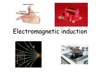
Electromagnetic Induction. emf is induced in a conductor placed in a magnetic field whenever there is a change in magnetic field. Moving Conductor in a Magnetic Field. http://www.ngsir.netfirms.com/englishhtm/Induction.htm.

E N D
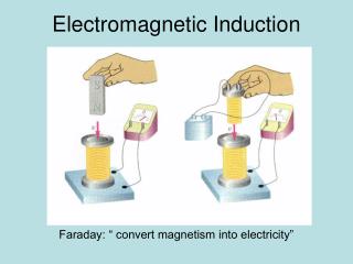
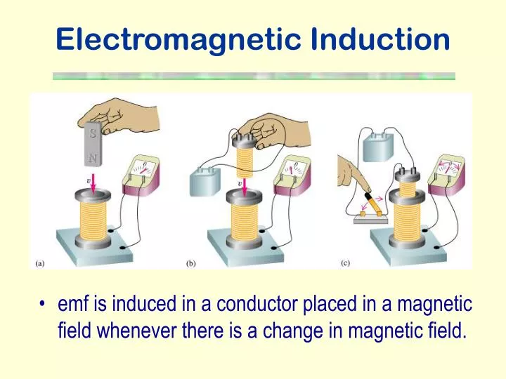
Electromagnetic Induction • emf is induced in a conductor placed in a magnetic field whenever there is a change in magnetic field.
Moving Conductor in a Magnetic Field http://www.ngsir.netfirms.com/englishhtm/Induction.htm • Consider a straight conductor moving with a uniform velocity, v, in a stationary magnetic field. • The free charges in the conductor experience a force which will push them to one end of the conductor. • An electric field is built up due to the electron accumulation. • An e.m.f. is generated across the conductor such that E = Blv.
Induced Current in Wire Loop • An induced current passes around the circuit when the rod is moved along the rail. • The induced current in the rod causes a force F = IlB, which opposes the motion. • Work done by the applied force to keep the rod moving is • Electrical energy is produced from the work done such that E = E It = W E= Blv
Lenz’s Law http://www.launc.tased.edu.au/online/sciences/physics/Lenz's.html • The direction of the induced current is always so as to oppose the change which causes the current.
Copper Pipe Experiment • This is a simplified diagram showing the areas of attraction and repulsion in this experiment. http://regentsprep.org/Regents/physics/phys08/clenslaw/default.htm
Lenz’s Law and Law of Conservation of Energy • Where does all the kinetic energy of the bar magnet go? • Well in fact, the Ek is transformed into electrical energy. • So this is the source of the emf, transferred from other energy into electrical energy. • Energy would be created from nothing if the induced current acted differently.
Magnetic Flux • The magnetic flux is a measure of the number of magnetic field lines linking a surface of cross-sectional area A. • The magnetic flux through a small surface is the product of the magnetic flux density normal to the surface and the area of the surface. Unit : weber (Wb)
Faraday’s Law of Electromagnetic Induction • The induced e.m.f. in a circuit is equal to the rate of change of magnetic flux linkage through the circuit. The ‘-’ sign indicates that the induced e.m.f. acts to oppose the change. http://www.physics.uoguelph.ca/applets/Intro_physics/kisalev/java/indcur/
Induced Currents Caused by Changes in Magnetic Flux • The magnetic flux (number of field lines passing through the coil) changes as the magnet moves towards or away from the coil. http://micro.magnet.fsu.edu/electromag/java/lenzlaw/index.html
Simple a.c. Generator • According to the Faraday’s law of electromagnetic induction, http://www.walter-fendt.de/ph11e/generator_e.htm
Back emf in Motors • When an electric motor is running, its armature windings are cutting through the magnetic field of the stator. Thus the motor is acting also as a generator. • According to Lenz's Law, the induced voltage in the armature will oppose the applied voltage in the stator. • This induced voltage is called back emf.
Armature coils, R Back emf, Eb Driving source, V Back emf and Power • So the mechanical power developed in motor MultiplyingbyI, then
I 0 Variation of current with the steady angular speed of the coil in a motor • The maximum speed of the motor occurs when the current in the motor is zero.
Po 0 Variation of output power with the steady angular speed of the coil in a motor • The output power is maximum when the back emf is ½ V.
I t 0 Variation of current as a motor is started The motor begins to move • As the coil rotates, the angular speed as well as the back emf increases and the current decreases until the motor reaches a steady state. Larger load Zero load
The need for a starting resistance in a motor • When the motor is first switched on, =0. • The maximum current, Io=V/R, very large if R is small. • When the motor is running, the back emf increases, so the current decrease to its working value. • To prevent the armature burning out under a high starting current, it is placed in series with a rheostat, whose resistance is decreased as the motor gathers speed.
Eddy Current • An eddy current is a swirling current set up in a conductor in response to a changing magnetic field. • Production of eddy currents in a rotating wheel
Applications of Eddy Current (1) http://micro.magnet.fsu.edu/electromag/java/detector/index.html • Metal Detector
Applications of Eddy Current (2) • Eddy current levitator • Smooth braking device • Damping of a vibrating system
Applications of Eddy Current (3) • Induction stove • Critical damping in the armature • of a moving-coil galvanometer.
How an induction stove works • The element's electronics power a coil that produces a high-frequency electromagnetic field. • The field penetrates the metal of the ferrous (magnetic-material) cooking vessel and sets up a circulating electric current, which generates heat. • The heat generated in the cooking vessel is transferred to the vessel's contents. • Nothing outside the vessel is affected by the field--as soon as the vessel is removed from the element, or the element turned off, heat generation stops.
Transformer http://micro.magnet.fsu.edu/electromag/java/transformer/index.html • A transformer is a device for stepping up or down an alternating voltage. • For an ideal transformer, • (i.e. zero resistance and no flux leakage)
Transformer Energy Losses • Heat Losses • Copper losses- Heating effect occurs in the copper coils by the current in them. • Eddy current losses- Induced eddy currents flow in the soft iron core due to the flux changes in the metal. • Magnetic Losses • Hysteresis losses- The core dissipates energy on repeated magnetization. • Flux leakage- Some magnetic flux does not pass through the iron core.
Designing a transformer to reduce power losses Thick copper wire Closed loop laminated iron core
Designing a transformer to reduce power losses • Thick copper wire of low resistance is used to reduce the heating effect (I2R). • The iron core is laminated, the high resistance between the laminations reduces the eddy currents as well as the heat produced. • The core is made of very soft iron, which is very easily magnetized and demagnetized. • The core is designed for maximum linkage, common method is to wind the secondary coil on the top of the primary coil and the iron core must always form a closed loop of iron.
Transmission of Electrical Energy • Wires must have a low resistance to reduce power loss. • Electrical power must be transmitted at low currents to reduce power loss. • To carry the same power at low current we must use a high voltage. • To step up to a high voltage at the beginning of a transmission line and to step down to a low voltage again at the end we need transformers.
Direct Current Transmission • Advantages • a.c. produces alternating magnetic field which induces current in nearby wires and so reduce transmitted power; this is absent in d.c. • It is possible to transmit d.c. at a higher average voltage than a.c. since for d.c., the rms value equals the peak; and breakdown of insulation or of air is determined by the peak voltage. • Disadvantage • Changing voltage with d.c. is more difficult and expensive.
Self Induction • When a changing current passes through a coil or solenoid, a changing magnetic flux is produced inside the coil, and this in turn induces an emf. • This emf opposes the change in flux and is called self-induced emf. • The self-induced emf will be against the current if it is increasing. • This phenomenon is called self-induction.
Definitions of Self-inductance (1) • Definition used to find L The magnetic flux linkage in a coil the current flowing through the coil. Where L is the constant of proportionality for the coil. L is numerically equal to the flux linkage of a circuit when unit current flows through it. Unit : Wb A-1 or H (henry)
Definitions of Self-inductance (2) • Definition that describes the behaviour of an inductor in a circuit Lis numerically equal to the emf induced in the circuit when the current changes at the rate of 1 A in each second.
Inductors • Coils designed to produce large self-induced emfs are called inductors (or chokes). • In d.c. circuit, they are used to slow the growth of current. • Circuit symbol or
Inductance of a Solenoid • Since the magnetic flux density due to a solenoid is • By the Faraday’s law of electromagnetic induction,
Energy Stored in an Inductor • The work done against the back emf in bringing the current from zero to a steady value Io is
Current growth in an RL circuit • At t = 0, the current is zero. • So • As the current grows, the p.d. across the resistor increases. So the self-induced emf ( - IR) falls; hence the rate of growth of current falls. • As t
Decay of Current through an Inductor • Time constant for RL circuit • The time constant is the time for current to decrease to 1/e of its original value. • The time constant is a measure of how quickly the current grows or decays.
- + emf across contacts at break • To prevent sparking at the contacts of a switch in an inductive circuit, a capacitor is often connected across the switch. The energy originally stored in the magnetic field of the coil is now stored in the electric field of the capacitor.
- + Switch Design • An example of using a protection diode with a relay coil. • A blocking diode parallel to the inductive coil is used to reduce the high back emf present across the contacts when the switch opens.
Non-Inductive Coil • To minimize the self-inductance, the coils of resistance boxes are wound so as to set up extremely small magnetic fields. • The wire is double-back on itself. Each part of the coil is then travelled by the same current in opposite directions and so the resultant magnetic field is negligible.