Download
1 / 13
0 likes | 83 Views
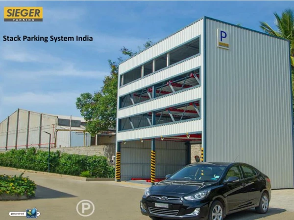
KLAUS stack parking systems are aimed to maximize the parking systems above ground/basement level. Easy to maintain, tailor-made and trustworthy. For More Information Click On :- https://www.klausindia.com/

E N D
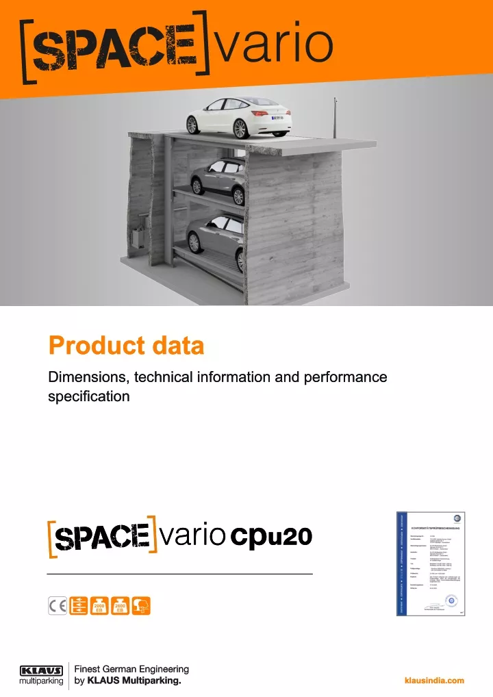
Product data Product data Dimensions, technical information and performance specification specification Dimensions, technical information and performance klausindia.com klausindia.com
Table of contents Explanation of symbols................................................................................2 Loading schedule.........................................................................................8 Parking positions..........................................................................................2 Access incline...............................................................................................8 Dimensions and tolerances..........................................................................3 Electrical installation.....................................................................................9 Overview of building configuration...............................................................3 CE conformity.............................................................................................10 Vehicle data..................................................................................................4 Technical information.................................................................................11 Overview of system types and building heights...........................................4 Performance specification..........................................................................12 Width dimensions.........................................................................................5 Services to be provided by the customer..................................................12 Detail of building configuration - pit floor.....................................................7 Subject to technical changes.....................................................................13 Detail of building configuration - pit edge....................................................7 Explanation of symbols Platforms accessible horizontally. max. load per parking space in kg. Upweighting over 2000 kg possible with surcharge (see "Vehicle data", page 4). Outdoor installation. The systems provided are consistent with DIN EN 14010 and the EC Machinery Directive 2006/42/EC. This system has also undergone a voluntary compliance test conducted by TÜV SÜD. Parking positions Parking space 2 lower Parking space 1 upper Upper parking space The lower vehicle can park in or leave the park- ing space. The lower vehicle can park in or leave the park- ing space. The upper parking space may be used under specific conditions. 2 Product data SpaceVario CPU20 EB 590.03.300 07/2020 English
Dimensions and tolerances All dimensions and minimum final dimensions. Tolerance for dimensions +3/-0. Dimensions in cm. In order to adhere to the minimum final dimensions, the tolerances in accordance with the German Construction Tendering and Con- tract Regulations [VOB], Part C (DIN 18330 and 18331) and DIN 18202 must also be taken into account. Note Overview of building configuration th Equipotential bonding from foundation earth connection to system (to be provided by the customer). The upper platform is a frame structure with sheet covering. The upper platform is accessible at ground level and when lowered (vehicle weight max. 2600 kg, wheel load max. 650 kg). The upper platform may be used as a parking space under specific conditions. 1 7 Slope with water collection channel (see "Detail of building configu- ration - pit floor", page 7, see "Drainage", page 12). 2 A separated maintenance shaft must be provided by the customer (with shaft cover, shaft ladder and access to the pit). Access to the maintenance shaft must be secured by the customer - consultation with KLAUS Multiparking required. The maintenance shaft also ac- commodates the hydraulic unit. 8 Pit edge (see "Detail of building configuration - pit edge", page 7). 3 In accordance with DIN EN 14010, the customer must provide 10 cm wide, yellow/black marking in accordance with DIN ISO 3864 in the access area along the edge of the pit to identify the hazard area. (see "Loading schedule", page 8). 4 530 cm for vehicle length max. 5.0 m 550 cm for vehicle length max. 5.2 m Shorter versions are possible on request - observe local regulations on parking space lengths. We recommend a pit length of 550 cm for comfortable use of your parking space and increasingly longer vehicles. 9 No fillets/haunches are permitted at the transition from the pit floor to the walls. If fillets/haunches are required, the systems must be narrower or the pits wider. 5 A protective grille is fitted to the areas at the side and rear; may be omitted under certain structural conditions. Consultation with KLAUS Multiparking required. 6 After operation, the system must be moved into the lowermost limit position (key blocking). Note 3 Product data SpaceVario CPU20 EB 590.03.300 07/2020 English
Vehicle data Version Clearance gauge SP (single platform) = 2 vehicles + 1 vehicle on the upper platform (see "Overview of building configuration", page 3) 160 30 45 55 Parking options 1 Series vehicles: saloon, estate, SUV, van in accordance with clearance gauge and maximum parking space load. 15° 13° 6° 100 125 2 For countries in which snow loads do not need to be taken into account: Vehicle width 190 cm with platform width 230 cm. Correspondingly wider vehicles can be parked with wider platforms. SP - upper parking space SP - lower parking space Weight Wheel load 2600 kg 650 kg 2000 kg 500 kg 2600 kg 650 kg For countries in which snow loads need to be taken into account, the parking option on the upper parking space is reduced in accordance with the table below: SP - upper parking space Weight Wheel load 2000 kg 500 kg Vehicle height (see "Overview of system types and building heights", page 4) 1 Vehicle length (see "Overview of building configuration", page 3) 2 The snow loads apply to a snow height of 20 cm. In the case of greater snow heights, the snow load must be cleared accordingly. Note Overview of system types and building heights If structural circumstances do not limit the height, the vehicle height on the upper parking spaces is not restricted. Note Vehicle height, lower Type GT H H CPU20 EB-425 CPU20 EB-495 425 495 385 455 165 200 GT H: Height extended GT: Pit depth 4 Product data SpaceVario CPU20 EB 590.03.300 07/2020 English
Width dimensions We recommend platform widths of minimum 250 cm and driving lane widths of 650 cm in order that vehicles can comfortably access the Multiparking system and enter and leave without difficulty. Note Narrower platforms may impede parking according to the following criteria. Driving lane width Entrance conditions Vehicle dimensions Observe minimum driving lane width in accor- dance with local regulations. 1 All side walls must be at a right angle. Deviation max. 1 cm! Attention: If the sides or rear are freely accessible, safeguards are required (barriers, protective grilles, marking, etc.). Measures will be determined on a project-by-project basis. Note Pit dimensions Plan view Closed pit Plan view Front view 2 20 Single platform - SP 80 60 SP Clear Platform width Single platform - SP platform width Parking levels Upper platform B 230 240 250 260 270 270 280 290 300 310 275 285 295 305 315 SP 1 A shaft cover must be provided (to be provided by the customer). 2 With dividing walls: Wall opening 15 x 15 cm. 5 Product data SpaceVario CPU20 EB 590.03.300 07/2020 English
Pit dimensions Single platform - SP Plan view Front view 2 20 2x single platform - SP without dividing walls 80 60 SP SP 2 20 with dividing walls Series system 80 60 3 3 SP SP SP 80 80 130 130 17.5 17.5 Clear 2x single platform without dividing walls Series system with dividing walls Platform width platform width Parking levels Upper platform C B 230 240 250 260 270 270 280 290 300 310 547.5 567.5 587.5 607.5 627.5 275 285 295 305 315 SP 1 A shaft cover must be provided (to be provided by the customer). 2 With dividing walls: Wall opening 15 x 15 cm. 3 The access to the adjacent system must have the same height as the access from the maintenance shaft to the pit. 6 Product data SpaceVario CPU20 EB 590.03.300 07/2020 English
Detail of building configuration - pit floor Drainage r r Detail of building configuration - pit edge A p y C p y . D S p 7 Product data SpaceVario CPU20 EB 590.03.300 07/2020 English
Loading schedule The systems are dowelled into the ground. The drill hole depth in the floor plate is approx. 15 cm, in the walls approx. 12 cm. The floor plate and walls must be from concrete (quality min. C20/25). The dimensions for the bearing points have been rounded. If the precise figures are required, please consult KLAUS Multiparking. Note Parking space load F1 F2 F3 F4 + 43.0 kN - 2.0 kN + 47.0 kN - 2.1 kN + 36.0 kN - 5.0 kN + 39.0 kN - 5.9 kN 2000 kg ± 14.4 kN ± 10.8 kN 2600 kg ± 15.0 kN ± 11.0 kN Width dimension B (see "Width dimensions", page 5) 1 Marking in accordance with DIN ISO 3864 (illustration colour not consistent with DIN ISO 3864) 2 The bearing capacity of the floor plate must be verified by a statistician. A thicker floor plate may be required in some cases. 3 Forces F3 and F4 should be reduced by 9 kN for wind-protected installation. 4 Access incline The maximum access inclines specified in the symbol sketch must not be exceeded. Improper configuration can lead to extreme difficulty accessing the system, for which KLAUS Multiparking cannot be held liable. Note max. 3% slope max. 10% gradient 8 Product data SpaceVario CPU20 EB 590.03.300 07/2020 English
Electrical installation Electrical installation diagram On-site facilities for operating element Surface-mounted operating element Electrical specifications (services to be provided by the customer) Nr. Quantity Designation Position Frequency 1 1 Power meter Pre-fuse: 3x safety fuse 25 A (slow-blow) or Circuit breaker 3x 25 A (trip characteristic K or C) Supply cable 5 x 4 mm² (3 PH+N+PE) with marked wires and protective earth Foundation earth connection Equipotential bonding in accordance with DIN EN 60204 from foundation earth connection to system Empty pipe EN 25 (M25) with taut wire Empty pipe EN 50 (M50) with taut wire Control stations in the supply cable 2 1 in the supply cable 1x per unit 3 1 to master switch 1x per unit 4 every 10 m Corner of pit floor 5 1 1x per system from pit floor to operating el- ement 6 1 1x per system 7 1 Supply cable to unit 1x per unit 8 1 1x per system from the supply cable into the shaft 9 1 Separate supply cable 230 V with lighting and socket 1x per system Electrical specifications (KLAUS Multiparking scope of supply) Nr. Designation 10 11 12 13 14 15 Switch cabinet with lockable master switch Control cable 3 x 0.75 mm² (PH+N+PE) Control cable 7 x 1 mm² with marked wires and protective earth Operating element Control cable 4 x 2.5 mm² with marked wires and protective earth Hydraulic unit 7.5 kW, three-phase current 230/400 V / 50 Hz 9 Product data SpaceVario CPU20 EB 590.03.300 07/2020 English
CE conformity The systems provided are consistent with DIN EN 14010 and the EC Machinery Directive 2006/42/EC. This system has also undergone a voluntary com- pliance test conducted by TÜV SÜD. 10 Product data SpaceVario CPU20 EB 590.03.300 07/2020 English
Technical information Usage area Corrosion protection The system is suitable for a fixed group of users as standard. Where users change (e. g. short-term parking in office buildings or hotels), structural modifications are required. Please request a consultation if re- quired. In accordance with the ‘Corrosion protection’ supplement. Protective grille If the permissible fall opening is exceeded, protective grilles must be installed on the systems. If there are roadways immediately adjacent to or behind the systems, the customer must provide barriers in accordance with DIN EN ISO 13857. This also applies during the construction stage. Units Low-noise, bearing-mounted hydraulic units are installed on rubber-metal blocks. Consequently, we recommend separating the garage body from the residential building. Noise protection Standard noise protection: In accordance with DIN 4109-1 Noise protection in high-rise: Maximum sound pressure level in living and sleeping areas 30 dB (A). User noise is not subject to the requirements (DIN 4109-1, Section 9). Ambient conditions Ambient conditions for the areas around Multiparking systems: Temperature range -20 to +40 °C. Relative humidity 50 % to a maximum external temperature of +40 °C. If ascent/descent times are specified, these relate to an ambient temperature of +10 °C and with the system positioned immediately adjacent to the hy- draulic unit. These times are increased at lower temperatures or with longer hydraulic lines. Wind zone 3 of 0.47 kN/m² in accordance with DIN EN 1991-1-4. Snow load zone 3 of 6.86 kN/m² in accordance with DIN EN 1991-1-3. Snow load data apply to the lowered system (see "Vehicle data", page 4) The following dimensions are required for adherence to this value: Noise protection package (KLAUS Multiparking) Sound insulation dimension of the building structure of min. R’w = 57 dB (service to be provided by the customer) in accordance with quote/order Increased sound protection (special agreement): In accordance with VDI 4100 Sound protection in high-rise: Maximum sound pressure level in living and sleeping areas 25 dB (A). User noise is not subject to the requirements (VDI 4100, Section 1). Building application documents The following dimensions are required for adherence to this value: Noise protection package (KLAUS Multiparking) Sound insulation dimension of the building structure of min. R’w = 62 dB (service to be provided by the customer) Note: User noise is noise that can be influenced individually by the user of our Multiparking systems. This includes, e.g., accessing the platform, the slamming of vehicle doors, engine and brake noise. Multiparking systems generally require approval. Please observe local reg- ulations and stipulations. in accordance with quote/order Care To prevent corrosion damage, please observe our special cleaning and care instructions and ensure that your garage is well ventilated. 11 Product data SpaceVario CPU20 EB 590.03.300 07/2020 English
Performance specification Description Lower platform comprising: Multiparking system for independent parking of 2 vehicles (single platform - SP), one on top of the other. The upper platform may be used as a parking space under specific conditions. Dimensions in accordance with the underlying pit, width and height dimen- sions. Access to the parking spaces horizontally (installation tolerance ± 1%). Special configuration of the lift and support structure prevents hindrance to door opening. Vehicle positioning in any parking space by positioning aid mounted on one side (to be adjusted in accordance with the operating instructions). Control via an operating element with key blocking by means of simultaneous key. Concise instructions at each operating point. Platform profiles Adjustable positioning aid Chamfered ramps Side beams Crossbeams Screws, nuts, washers, spacers, etc. Hydraulic system comprising: Hydraulic cylinders Magnetic valves Hydraulic lines Bolted connections High-pressure hoses Attachments Multiparking system comprising: 2 telescopic lifting columns at the rear with hydraulic cylinder (secured to the floor) 2 telescopic lifting columns at the front (secured to the floor) 1 upper platform/cover with platform profiles from KLAUS Multiparking 2 lower platforms 1 mechanical synchronisation system (for synchronised operation of the hydraulic cylinders when lifting and lowering) 2 hydraulic cylinders Dowels, screws, connectors, bolts, etc. The platforms are continuously accessible. Electrical system comprising: Operating element (emergency-stop, key, 1 simultaneous key per parking space) Switch cabinet with lockable master switch Hydraulic unit comprising: Hydraulic unit (low-noise, fitted to bracket and bearing mounted on rub- ber-metal block) Hydraulic oil tank Oil filling Internal gear pump Pump holder Coupling Three-phase motor Noise protection, motor protection switch and control fuse Test pressure gauge Pressure relief valve Hydraulic hoses (to attenuate noise transmission to the hydraulic pipes) Upper platform comprising: Platform profiles Adjustable positioning aid Cover sheets Side beams Crossbeams Screws, nuts, washers, etc. Services to be provided by the customer Barriers Drainage Barriers that may be required in accordance with DIN EN ISO 13857 to se- cure the pits where there are roadways immediately in front of, adjacent to or behind the systems. This also applies during the construction stage. Pro- tective grilles on the systems, where required, are available for a surcharge. Functional drainage of the pit must be provided by means of a floor drain in the centre area that is connected to the sewer system or a pump sump. The water must be drained away by a pump provided by the customer. A slope from the corners of the pit/supporting surface of the lifting columns to the floor drain/pump sump is required. In the interests of environmental protection, we recommend coating the pit floor. Oil and/or fuel separators should be installed in accordance with local regulations. To drain large quantities of water from the yard area, the customer must install a water collection channel around the outside of the pit. Parking space numbering Parking space numbering, if required. Building services systems Warning marking Any lighting, ventilation, fire-extinguishing and fire-alarm systems that may be required, plus clarification and compliance with corresponding official doc- umentation. In accordance with DIN EN 14010, the customer must provide 10 cm wide, yellow/black marking in accordance with DIN ISO 3864 in the access area along the edge of the pit to identify the hazard area. Lighting Wall openings The customer must observe local regulations pertaining to the illumination of parking spaces and roadways. In accordance with DIN EN 12464-1 ‘Light and lighting - Lighting of work places’, an illumination level of min. 200 lx is recommended for the parking spaces and operating area of the system or of min. 50 lx for the maintenance shaft. Any wall openings that may be required should be in accordance with the sectional drawings (see "Width dimensions", page 5). 12 Product data SpaceVario CPU20 EB 590.03.300 07/2020 English
Supply cable to master switch - foundation earth Installation The customer must lay the supply cable to the master switch during assem- bly. Functional capability can be checked by our engineers on site, in con- junction with the electronics engineer. If this is not possible during assembly for reasons attributable to the customer, the customer must commission an electronics engineer. The customer must earth the steel structure with a foundation earth connec- tion (earthing distance max. 10 m) and equipotential bonding in accordance with DIN EN 60204. In general, the customer must provide a crane to aid installation of the tele- scopic lifting columns. Hook height min. 700 cm above entrance level, crane load approx. 1400 kg. Maintenance shaft A separated maintenance shaft (with shaft cover, shaft ladder and access to the pit) must be provided by the customer. A common maintenance shaft may be sufficient for series systems, depending on the project. Operating element Ventilation The customer must provide an empty pipe (see "Electrical installation", page 9) from the pit floor to the operating element. The position of the oper- ating element should be determined on a project-by-project basis (operating stands, house wall, etc.). To ensure a continuous exchange of air, to reduce air humidity, prevent con- densation and reduce vehicle moisture (from rain, snow, ice, etc.), we rec- ommend that the customer provide a ventilation system in conjunction with a HVAC engineer. This will help to minimise the risk of corrosion and resulting faults. Subject to technical changes In the course of technical progress, KLAUS Multiparking shall be entitled to use newer or different technologies, systems, processes or standards to pro- vide the services than initially offered, provided that this does not disadvantage the customer in any way. Manufacturer: Sales office: KLAUS Multiparking systems pvt. ltd NKB House Survey No.98, Plot No.14 Bhusari Colony, Pune 41 1038 590.03.300 07/2020 English SpaceVario CPU20 EB Fon: +91 20 6681 5800/1 Fax: +91 20 6681 5805 Product data sales@klausmultiparking.in www.klausindia.com klausindia.com