Download
1 / 33
460 likes | 1.68k Views
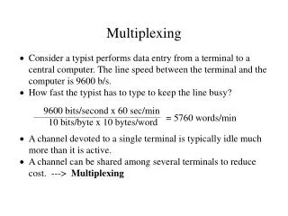
Multiplexing. 3/9/2009. Multiplexing. Multiple links on 1 physical line Common on long-haul, high capacity, links More cost effective when multiplexing is used Include frequency division multiplexing, time division multiplexing, code division multiplexing. Multiplexing Techniques.

E N D
Multiplexing 3/9/2009
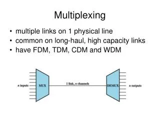
Multiplexing • Multiple links on 1 physical line • Common on long-haul, high capacity, links • More cost effective when multiplexing is used • Include • frequency division multiplexing, • time division multiplexing, • code division multiplexing.
Multiplexing Techniques FDM TDM CDM
FDM • Analog signaling is used to transmits the signals. • Examples: • Broadcast radio and television, • cable television, • the AMPS cellular phone systems • The oldest multiplexing technique. • It involves analog signaling, it is more susceptible to noise.
FDM – Basic Operation Analog Signals Summed Summed Subcarriers • Multiple signals can be modulated using different frequencies • Signals with different frequencies can be Multiplexed together • The multiplexed signal has a center frequency and bandwidth • Larger than total BW of all multiplexed signals Shifted in frequency No overlap B=Total BW
FDM – Example • Transmitted TV signal • Total BW is 6 MHZ • Audio carrier operating at fca at f0+5.75 • Color subcarrier operating at fcc at f0+4.799545 MHz • Video subcarrier operating at fvc at f0+1.25 MHz • CATV has a bandwidth of about 500 MHZ • Many channels can be multiplexed together!
FDM – Multiplexing three voice signals • Voice signal has a range of 300-3400 KHz • Recall FM Carrier Freq. Lower Sideband Upper Sideband s1 Fc-Bw Fc+Bw
Analog Carrier Systems • long-distance links use an FDM hierarchy • AT&T (USA) and ITU-T (International) variants • Group • 12 voice channels (4kHz each) = 48kHz • in range 60kHz to 108kHz • Supergroup • FDM of 5 group signals supports 60 channels • on carriers between 420kHz and 612 kHz • Mastergroup • FDM of 10 supergroups supports 600 channels • so original signal can be modulated many times
Analog Carrier Systems 4KHz each Range
Wavelength Division Multiplexing • FDM with multiple beams of light at different frequency • carried over optical fiber links • commercial systems with 160 channels of 10 Gbps • lab demo of 256 channels 39.8 Gbps • architecture similar to other FDM systems • multiplexer consolidates laser sources (1550nm) for transmission over single fiber • Optical amplifiers amplify all wavelengths • Demux separates channels at the destination • also have Dense Wavelength Division Multiplexing (DWDM)
Synchronous Time Division Multiplexing • The original time division multiplexing. • The multiplexor accepts input from attached devices in a round-robin fashion and transmit the data in a never ending pattern. • T-1 and ISDN telephone lines are common examples of synchronous time division multiplexing.
TDM Link Control • no headers and trailers • data link control protocols not needed • flow control • data rate of multiplexed line is fixed • if one channel receiver can not receive data, the others must carry on • corresponding source must be quenched • leaving empty slots • error control • errors detected & handled on individual channel
Another Example • Byte interleaving • Characters are shuffled! • The receiver reassembles each channel
Pulse Stuffing • Reasons • synchronizing data sources • having clocks in different sources drifting • having data rates from different sources not related by simple rational number • Pulse Stuffing a common solution • have outgoing data rate (excluding framing bits) higher than sum of incoming rates • stuff extra dummy bits or pulses into each incoming signal until it matches local clock • stuffed pulses inserted at fixed locations in frame and removed at demultiplexer
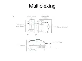
Example – TDM of analog and digital sources with different transmission rates Analog 1 Analog Sampler A/D Converter
Example – TDM of analog and digital sources with different transmission rates Conversing Analog To Digital 1 Analog Sampler A/D Converter
Example – TDM of analog and digital sources with different transmission rates Digital R’ Digital R Digital Signal Pulse Stuffing Digital
Example – TDM of analog and digital sources with different transmission rates 16 Bits 32 Bits 2 Bit Each Note: Voice signal, hence minimum BW requirement is 4KHz per bit
Digital Carrier Systems • long-distance links use an TDM hierarchy • AT&T (USA) and ITU-T variants • US system based on DS-1 format • can carry mixed voice and data signals • 24 channels used for total data rate 1.544Mbps • each voice channel contains one word of digitized data (PCM, 8000 samples per sec) • same format for 56kbps digital data • can interleave DS-1 channels for higher rates • e.g., DS-2 is four DS-1 at 6.312Mbps
DS-1 Transmission Format ; Bit 8 indicated voice or data (6x8KHz or 5x9.6KHz or 10x4.8 KHz) – The first bit is used to indicate the subrate
Statistical TDM • in Synch TDM many slots are wasted • Statistical TDM allocates time slots dynamically based on demand • multiplexer scans input lines and collects data until frame full • line data rate lower than aggregate input line rates • may have problems during peak periods • must buffer inputs
Comparing Synchronous and Statistical TDM Frame Format Each slot has channel ID and possibly message length information http://www.trendcomms.com/multimedia/training/broadband%20networks/web/main/m2/temari/seccio9/t1e1.htm
Performance of Statistical TDM • Refer to your notes.
Asymmetrical Digital Subscriber Line (ADSL) • link between subscriber and network • uses currently installed twisted pair cable • is Asymmetric - bigger downstream than up • uses Frequency division multiplexing • has a range of up to 5.5km • Its underlying technology is Discrete Multitone (DMT) http://www.cs.tut.fi/tlt/stuff/adsl/node6.html#kuspektri
High-bit-rate Digital Subscriber Line (HDSL) – Connecting the subscriber to the PSTN http://www.thenetworkencyclopedia.com/d2.asp?ref=872
Discrete Multitone (DMT) • A multiplexing technique commonly found in digital subscriber line (DSL) systems • The basic idea of DMT is to split the available bandwidth into a large number of subchannels • DMT then combines hundreds of different signals, or subchannels, into one stream • Each subchannel is quadrature amplitude modulated (recall - eight phase angles, four with double amplitudes) • Theoretically, 256 subchannels, each transmitting 60 kbps, yields 15.36 Mbps. Unfortunately, there is noise.
Discrete Multitone (DMT) • Idea: If some subchannel can not carry any data, it can be turned off and the use of available bandwidth is optimized High attenuation at higher frequencies http://www.cs.tut.fi/tlt/stuff/adsl/node22.html#kudmtex
Discrete Multitone (DMT) – How… • On initialization, the DMT modem sends test signals to each subchannel to determine its S/N • Channels with higher S/N receive more bits • Each subchannel is quadrature amplitude modulated (recall - eight phase angles, four with double amplitudes)