Download

1 / 21
310 likes | 1.4k Views
Analog to Digital Conversion. Introduction. An analog-to-digital converter ( ADC , A/D , or A to D ) is a device that converts continuous signals to discrete digital numbers

E N D
Introduction • An analog-to-digital converter(ADC, A/D, or A to D) is a device that converts continuous signals to discrete digital numbers • In electronics, a digital-to-analog converter(DAC or D-to-A) is a device for converting a digital (usually binary) code to an analog signal (current, voltage or charges). Digital-to-Analog Converters are the interface between the abstract digital world and the analog real life. Simple switches, a network of resistors, current sources or capacitors may implement this conversion
Important terminologies in ADC • Resolution • Response type • Linear ADCs • Non-linear ADCs • Accuracy • Sampling rate • Aliasing
Resolution • The resolution of the converter indicates the smallest analog value that it can convert to a digital number • If the ADC has 8 bits and the Full scale is 0-5 Volts, then the ADC voltage resolution is: • 5/28 = 0.01953125 Volts
Response type • Linear ADCs • Output binary value changes approximately with the analog value within the resolution (or ½ the resolution) • Non-linear ADCs • Uses techniques known as companding to ‘magnify” the low amplitude analog signals • m-law • A-law • Dolby
Accuracy • Accuracy depends on • Quantization error • Non-linear error caused by the physical imperfections of ADC
Sampling rate • For ADC, a signal values are measured and stored at intervals of time Ts, the sampling time. • A bandlimited analog signal must be sampled at a frequency fs = 1/Ts that is twice the maximum frequency (fa) of the bandlimited signal • fs = 2fa is known as the Nyquist Sampling frequency
Aliasing • If a signal values are measured and stored at frequencies greater than the Nyquist sampling rate, the signal can be reproduced exactly (within quantization and other non-linear error accuracy). • However, If a function is sampled at less than Nyquist rate, the resulting function may have different frequency content. This is known as aliasing. • For example: If a 3 KHz sine wave is sampled at 4 KHz, the resulting signal will appear as a 1 KHz signal.
How is it doneDigital-Ramp ADC http://hyperphysics.phy-astr.gsu.edu/HBASE/Electronic/adc.html
How is it doneSuccessive Approximation ADC http://hyperphysics.phy-astr.gsu.edu/HBASE/Electronic/adc.html
How is it doneFlash ADC http://hyperphysics.phy-astr.gsu.edu/HBASE/Electronic/adc.html
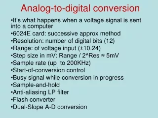
Analog to Digital chip: ADC0820 • 8-Bit High Speed µP Compatible A/D Converter with Track/Hold Function • Uses ½ flash conversion technique • consists of 32 comparators • a most significant 4-bit ADC • a least significant 4-bit ADC • 1.5 µs conversion time • Does not need external sample-and-hold for signals moving at less than 100 mV/µs.
Analog to Digital chip: ADC0820 • Has many input modes, RD, WR-RD, WR-RD Standalone • Input pulse required to read analog data (Sample) • Must sample at more than Nyquist rate (fs = 2*fa) • Outputs signal when data is valid
ADC0820 – WD-RD Mode t1 = tINTL= 800 ns
ADC0820 – WD-RD Mode t1 = tINTL= 800 ns
Acquiring an Analog Signal • Input is a sinusoidal signal with peak to peak of 5 V • Voltage input in the range -2.5 to 2.5 V • Use Analog to Digital Converter ADC0820 • Input’s analog voltage 0 to 5 V • Requires adding 2.5 Volts to input signal before converted.
Op-Amp - Non-Inverting Adder • Use LM741 Operational Amplifier • Eqs: Vo =V1 + v2 (for all resistors equal) Vo = (R1+R2)/R2 (V1 R4 + V2R3)/ (R3+R4)
References • http://en.wikipedia.org/wiki/Analog_to_digital_converter • http://hyperphysics.phy-astr.gsu.edu/HBASE/Electronic/adc.html