Download
1 / 33
400 likes | 1.2k Views
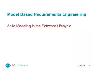
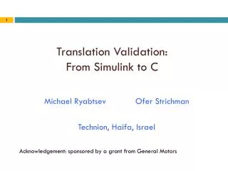
Model Based Development: From system engineering with Simulink to software specification with SCADE then to implementation. Thierry LE SERGENT FERIA May 4 th , 2004. Agenda. Model based development Simulink vs. SCADE Principles of Simulink Gateway. Context. System design with Simulink

E N D
Model Based Development:From system engineering with Simulink to software specification with SCADEthen to implementation Thierry LE SERGENT FERIA May 4th, 2004
Agenda • Model based development • Simulink vs. SCADE • Principles of Simulink Gateway Esterel Technologies, 2004
Context • System design with Simulink • Goal: develop software for the Controller Plant to be controlled Controller: Software to be implemented HW interface HW interface Electronic system to be implemented Esterel Technologies, 2004
Software development • Traditional method • Modelisation in Simulink for simulation • Hand coding of the software controller • Inconveniences • Coherence between Model and Code • Round trip is difficult Esterel Technologies, 2004
Model based development • First solution • Code generation from the Simulink model • Advantages: model based a single reference: the Simulink model coherence, fast round trip, etc. • Inconvenience: Simulink model not a formal description (see next slides) • New solution • Assisted translation • From Simulink model • To formal description language SCADE • Then code generation from SCADE • Advantages: • Model based (fast round trip if translation automatized) • Formal software specification No ambiguities, Formal verification, etc. Esterel Technologies, 2004
Workflow System Engineering Software Specification Software Implementation SCADE Specification Simulink model SCADE Simulink Gateway SCADE Implementer SCADE implementation Engineering to specification Specification to implementation C code Esterel Technologies, 2004
Different Tools for Different Purposes • SCADE and Simulink are both model based development tools, but they are targeted for different purposes • Simulink: Simulation environment • Primarily an environment for prototyping. Excellent at quickly representing graphically numerical equations/control laws, and simulating them • Extremely flexible. Requires no programming constraint • But not designed to generate safe code • SCADE: SW Design environment for critical control systems • SCADE has been designed from the beginning to meet the strongest embedded software requirements, in particular for safety critical systems in avionics • SCADE offers a fully integrated design environment from specification to safe embedded production code certifiable to strict industry standards (DO178B) Esterel Technologies, 2004
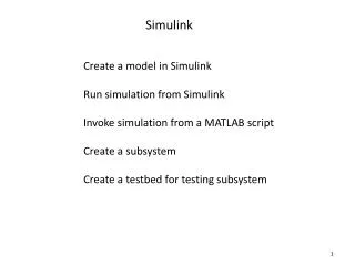
Simulink SCADE C code generation & embedding From Simulink to SCADE • Modelling of environment (system) + controller • Simulation of the whole system • Validation of the controller model • Code generation • The translation must: • Explicit some implicit behavior • Filter unsafe constructs • Compute types and clocks
Pb1: Simulink initial values • Initial values • Implicitly determined from the content of the sub-system • can lead to misunderstandings • On this model, only the Unit Delay has an initial value = 3Gain block has no initial value Simulink sets the output to 0 3 * 2 = 0 !! Esterel Technologies, 2004
Pb1: SCADE initial values • It is mandatory to explicitly set initial output values of an enabled sub-system • Independent of the content of the sub-system • No automatic change out of control of the designer, sono unexpected calculated values Initial value of the first output Initial value of the second output Esterel Technologies, 2004
Pb 2: Unsafe Operators • Simulink • Some operators are not usable for the development of critical embedded software because they can result in non deterministic or misleading behavior • Simulink blocks: • Merge: indeterminist block, except in special cases • Goto/From, Data Store : equivalent to global variables, make the design hard to understand and not robust for enhancements • While loops: could lead to infinite loops • SCADE • SCADE has been designed from the beginning with safety objectives: only safe and deterministic operators exist • The SCADE language, based on Lustre academic languagemakes it impossible to create a non deterministic design Esterel Technologies, 2004
Unsafe Operators: Merge • The Merge block combines its inputs into a single output line whose value at any time is equal to the most recently computed output of its driving blocks • On this example, both sub-systems are running in parallel and it is not possible to determine which output the Merge block will give, the square or the sinus • The Merge block is determinist when all its inputs are strictly exclusives, for example when generated by an action block of the If/Then/Else or Switch/Case blocks Supported by Simulink Gateway Esterel Technologies, 2004
Pb 3: Modularity • Simulink • “Virtually” modular: only visual grouping • Subsystem behaviour depends on this usage within the system • No clear subsystem interface definition • A subsystem re-used in another project can behave differently, it must be re-validated • SCADE • Truly modular: a SCADE design is composed of independent node designed separately • A node always behaves in the same way, independently of where it is used • A SCADE node has a strong interface definition • A node can be directly re-used in another project without any additional work Esterel Technologies, 2004
Pb 4: SW Simulation • Simulink • The model is interpreted as a Mathematical set of equations, an Ordinary Differential Equations (ODE), solved at each simulation step by the solver • Simulation results are highly dependant of the solver (integration algorithm) resulting in different behaviors for different solvers • Discrete time does not exist, it is interpreted as piece wise constant continuous time: this is different from SW behavior • SCADE • Everything in SCADE is based on a cyclic logical time, counted as discrete instants which enables exactly the same behavior as a SW application • This is an execution of the generated code (Software In the Loop simulation) • No difference between simulation and generated code Esterel Technologies, 2004
Simulink to SCADE translation • Filtering unsafe constructs • Unsafe blocks translated into undefined imported nodes • Interpretation of the Simulink model • Discrete time, fixed-step solver • Translation of the Controller of the Simulink model a SCADE model with same interface • Structure kept: Subsystem Node • Graphical look kept: Simulink net view SCADE net view • Names kept: variables, operators, … • Mapping: Simulink predefined operator SCADE node • Configurable mapping to SCADE librarie node(generated node for a few specific cases) • Mapping dependant from datatype computed Esterel Technologies, 2004
Simulink model example Esterel Technologies, 2004
Simulink model format • Simulink .mdl files: • Basically 3 kind of objects: • System {…} • -> Hierarchy • Block {…} • List of: “AttributeName” = “value” • First attribute: “BlockType” • Line {…} Esterel Technologies, 2004
.mdl example System { Name "sys NOT" Location [107, 120, 513, 367] … Block { BlockType Constant Name "Constant" Position [25, 40, 130, 80] Value "2.5 * AA" } … Block { BlockType Logic Name "Logical\nOperator" Position [185, 34, 280, 86] Operator "NOT" … } … Line { SrcBlock "Logical\nOperator" SrcPort 1 DstBlock "Out1" DstPort 1 } Esterel Technologies, 2004
Type inference • Simulink • No data type specified, i.e. all data flows are of type « double » • Flat vectors possible almost everywhere (vectorized blocks) • Scade: all flows must be typed; • Basic types: bool (noted b), int (i), real (r) • Tuples • For precise software specification, SCADE types must be computed • For formal verification, an « int » is very different from a « real » • Note: In Simulink, it is possible to specify very precise datatype such as int8, uint16, etc. for code generation • This coding step should be handled after the software specification phase • This step is handled by the new SCADE implementer tool Esterel Technologies, 2004
Principles • Always compute the smallest types (bool < int < real) • Start from the value of the static expressions (also for Matlab variables) • “Propagate” the types on the flow • Show the result on a decompiled, annotated Simulink model Esterel Technologies, 2004
Configuration file • For each Simulink block • How propagate the types ? • Translation to which SCADE node ? • Depend of • The BlockType, and attributes of the block (ex: “operator”=“NOT”, or…) • The types inferred for the input • First example from Main Configuration File: ( "BlockType" = "Logic", "Operator" = "NOT" ) { Interface( 1, 1) Type( b -> b) {"SC_ECK_NOT"} // SCADE predefined NOT operator Type( i -> b) { "LibSimulink", "SMLK_NotI"} Type( r -> b) { "LibSimulink", "SMLK_NotR"} } Esterel Technologies, 2004
Resulting SCADE model • Note: Parameterization with Matlab variable AA kept • Each Matlab variable translated into a SCADE constant Esterel Technologies, 2004
Set of mapping rules • When the types input does not match CF rules • Choice of the « nearest » rule with larger types • Introduction of explicit cast: always from a smaller type to a bigger one • Example: • SCADE model Esterel Technologies, 2004
Set of mapping rules ( "BlockType" = "Switch") { Interface( 3( "Threshold"), 1) Type( b, r, b ( r) -> b) { "LibSimulink", "SMLK_Switch"} Type( i, r, i ( r) -> i) { "LibSimulink", "SMLK_Switch"} Type( r, r, r ( r) -> r) { "LibSimulink", "SMLK_Switch"} } • The « nearest rule » must be unique ! • Non coherent example: • Problem if (i, i) inferred for the inputs. The 2 rules are “equally near” • A set of rule is « coherent » if the min of any 2 rules is in the set • Min computed with b < i < r input per input • Error message: add rule « type…. » or remove one of rules « type… », « type… », … Type( i, r -> i) { "Lib1", "N1"} Type( r, i -> r) { "Lib2", "N2"} Esterel Technologies, 2004
Vectorization • When the input types are vectors • Vectorization of the mapping rule • Automatic introduction of SCADE textual capsule that apply the operator as many time as necessary, and build the vectors to output Esterel Technologies, 2004
Vectorization capsule node S2S_Vect_3_DeadBandUnSymm( Input1 : [bool , int , real] ; hidden Input2 : real ; hidden Input3 : real) returns ( Output1 : [real , real , real]) ; var …. let equa S2S_Vect_3_DeadBandUnSymm[ , ] _L0 = Input1[1] ; _L1 = Input1[2] ; _L2 = Input1[3] ; _L3 = BoolToReal(_L0) ; Out_1_1 = DeadBandUnSymmetrical(_L3 , Input2 , Input3) ; _L4 = real (_L1) ; Out_2_1 = DeadBandUnSymmetrical(_L4 , Input2 , Input3) ; Out_3_1 = DeadBandUnSymmetrical(_L2 , Input2 , Input3) ; Output1 = [Out_1_1 , Out_2_1 , Out_3_1] ; tel ; Esterel Technologies, 2004
Type inference algorithm • Fix-point algorithm to propagate throughout the model - the arities (size of the vectors),- the types,thanks to the « main » and « user defined » Configuration Filesspecifying mapping rules. • Problems: the loops in the data flow • Message « ATI failed » • Workaround: the Configuration Files:it is possible to « force the types » thanks to rules in CF • Example: • Vérimag is working on another strategy • Constraints resolution algoritm (« propagation » in both direction of the data flow) “Controller”/ "UnitDelay"{ interface(1,1) ArityType(r -> r) } Esterel Technologies, 2004
Clock inference (1/3) • Simulink • Discrete operators: execution based on “sample time” • Value representing an actual delay • "-1" to represent inheritance of the sample time from the input flow • Enable subsystems • Excuted while condition signal > 0 • Triggered subsystems • Executed on rising/falling edge of condition signal • SCADE • clocks derived from a basic clock • Condact operator on node • Executed if condition signal = TRUE Esterel Technologies, 2004
Clock inference (2/3) • Simulink Gateway • computes the rate of the SCADE basic clock: • GCD of the sample time values.Example: ST1=1.75, ST2=(2.25, 0.5) Basic Clock=0.25 • generates all required derived clocks • SCADE node SMLK_ClockGen(period,offset) (period,offset) = (9,2) for the block with ST2 • Encapsulates the SCADE node corresponding to Simulink discrete block with condact activated by the correct generated clock Esterel Technologies, 2004
Clock inference (3/3) • Enable and trigger handling • Encapsulate the SCADE node with condact activated by signal computed from the condition • E.g.: GeneralTrigger = RisingEdge(condition); • Caution: the generation of the derived clock (by SMLK_ClockGen) must be done OUTSIDE Enabled or Triggered subsystems;The « global time » runs always at the same speed • Derived clocks generated in a textual capsule at the root node of the model • Propagation of the clocks to the discrete blocks through additional parameters to the nodes Esterel Technologies, 2004
From SCADE to Simulink: Simulink Wrapper Back box Simulation Simulink Gateway Original Simulink model “Hybrid model” SCADE CG C files MEX Simulink Wrapper S-function DLL Generated SCADE model Wrapper code (C) Esterel Technologies, 2004
Simulink Wrapper • The SCADE model is integrated into Simulink as an “S-Function” • The S-Function is automatically generated : • C code generated by the SCADE Code Generator • Capsule code generated by the Wrapper • Simulation under Simulink: • The SCADE node is a black box • Next release: also white box co-simulation with SCADE simulator • The embeddable code interacts with Simulink environment • May be used Independently or coupled with Simulink translator Esterel Technologies, 2004
Simulink Gateway project summary • Started: February 2000 • under European project SafeAir (SNECMA, Airbus, Vérimag, …) • Pursued under European project RISE (Audi, TTTech, Vérimag) • Matured tool used on industrial projects • Example: New Rafale engine developed by Hispano Suiza • Several thousands of Simulink blocks • Code generated by SCADE KCG for certification this year Esterel Technologies, 2004