Download
1 / 45
450 likes | 477 Views
Chapter 14 Local Area Networks. Prof. Choong Seon HONG. Introduction. Three Generations of Ethernet. 14.1 Traditional Ethernet. Mac Sublayer Physical Layer Physical Layer Implementation Bridged Ethernet Switched Ethernet Full-Duplex Ethernet. Traditional Ethernet.

E N D
Chapter 14 Local Area Networks Prof. Choong Seon HONG
Introduction • Three Generations of Ethernet
14.1 Traditional Ethernet • Mac Sublayer • Physical Layer • Physical Layer Implementation • Bridged Ethernet • Switched Ethernet • Full-Duplex Ethernet
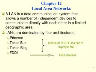
Traditional Ethernet • Designed to operate at 10 Mbps • Access through CSMA/CD • Media shared between all stations
802.3 MAC frame • Preamble – 7 bytes of alternating 0s and 1s to alert the receiver and allow it to synchronize • Start Frame Delimiter (SFD) – 1 byte – 10101011 signals the beginning of a frame, last chance for synchronization – last 2 bits are 11 • Destination address (DA) – 6 bytes – contains the physical address of the destination station or stations • Source address (SA) – 6 bytes – contains the physical address of the sender • Length/type – if less than 1518 then it defines the length of the data field – if more than 1536 then it defines the type of the PDU packet that is encapsulated • Data – data encapsulated from upper-layer protocols : 46 ~ 1500 bytes • CRC – CRC-32
Addressing • Ethernet addresses in hexadecimal notation • Each station on an Ethernet network has its own network interface card (NIC) • NIC provides the station with a 6-byte physical address
Unicast and Multicast and Broadcast Address • Source address is always unicast • Destination can be unicast, multicast, or broadcast • Unicast specifies one recipient • Multicast specifies multiple recipients • Broadcast sends to all stations on the network – destination address is forty-eight 1s
Physical Layer • Physical layer for 10-Mbps Ethernet
Physical Layer Signalling(PLS) • PLS sublayer encodes and decodes data • Using Manchester Encoding • Data rate of 10 Mbps
Attachment Unit Interface (AUI) • A Specification that defines the interface between the PLS and MAU. • Developed to create a kind of medium-independent interface interface.
Medium Attachment Unit (MAU) • MAU (transceiver) : transmitter and receiver • Transmitting signals over the medium; receiving signals over the medium; detecting collisions • Medium dependent • Transceiver is a transmitter and receiver, can be external or internal • Position and Functions of a Transceiver
Medium Dependent Interface (MDI) • To connect the transceiver (internal, external) to medium, we need a MDI. • For an external transceiver, it can be a tap or a tee connector. • For an internal transceiver, it can be a jack.
Physical Layer Implementation • Categories of traditional Ethernet
10Base5 : Thick Ethernet • thick Ethernet or Thicknet • bus topology, external transceiver • Connection of a station to the medium using 10Base5
10Base2 : Thin Ethernet • Connection if stations to the medium using 10Base2 • Thin Ethernet or Cheapernet • bus topology, internal transceiver or a point-to-point connection via an external transceiver
10Base-T : Twisted Pair Ethernet • physical star topology • stations connected to a hub with internal or external transceiver
10Base-FL : Fiber Link Ethernet • fiber link Ethernet • uses star topology to connect stations to a hub • normally implemented with external transceiver having two pairs of fiber-optic cables connecting it to the hub
Bridged Ethernet • Raising the bandwidth • Separating collision domains
Raising the Bandwidth • A Network with and without a Bridge • 10/6 Mbps vs 10/12 Mbps in case that traffic is not going through the bridge
Switched Ethernet • Bandwidth is shared only between the station and the switch (5 Mbps each) • N-port switch; Switched Ethernet
Full-Duplex Ethernet • A Limitation of 10Base5 and 10Base2 half-duplex. • Evolution : switched Ethernet full duplex Switched Ethenet • 10Base-T is always Full-duplex. • Full duplex mode increases the capacity of each domain from 10 to 20 Mpbs.
Full-Duplex Ethernet • No need for CSMA/CD, this functionality can be turned off. • Each link is a point-to-point dedicated path between the station and the switch. • For flow and error control • Adding a sublayer called MAC Control between MAC sublayer and LLC sublayer
14.2 Fast Ethernet • Evolution from 10 to 100 Mpbs doesn’t change the MAC sublayer. • Access method is CSMA/CD, which is kept for backward compatibility. • Frame format, minimum and maximum frame lengths, and addressing are the same.
Autonegotiation • Allowing two devices to negotiate the mode or data rate of operation. • To allow incompatible devices to connect to one another. For example, between 10 Mbps-device and 100 Mbps-device • To allow one device to have multiple capabilities • To allow a station to check a hub’s capabilities
Reconciliation • Replacing PLS sublayer in 10 Mbps Ethernet • But, encoding and decoding, which were performed by the PLS, are moved to the PHY sublayer (transceiver), because encoding in Fast Ethernet is medium-dependent. • Is responsible for passing of data in 4-bit format (nibble) to the MII.
MII • The AUI is replaced with the medium-independent interface (MII) • Can be used with both a 10-and 100Mbps data rate • Features a parallel data (4 bit at a time) path between the PHY sublayer and the reconciliation sublayer
PHY (Transceiver) and MDI • Transceiver is responsible for encoding and decoding. • MDI is need to connect the transceiver to the medium.
100Base-TX Implementation • Uses two pairs of twisted-pair cable • Physical star topology • Internal or external transceiver • Transceiver – responsible for transmitting, receiving, detecting collisions, and encoding/decoding data
Encoding and decoding in 100Base-TX • Encoding/decoding – first performs block encoding using 4B/5B, then encoded using MLT-3 (multiline transmission, three level)
100Base-T4 • uses category 3 (voice-grade twisted pair) or higher UTP • uses 4 pairs • Encoding/Decoding – 8B/6T
Giga-bit Ethernet • No longer possible to keep the MAC sublayer untouched • Two distinctive approaches: half-duplex using CSMA/CD or full-duplex with no need for CSMA/CD
Physical Layer in Gigabit Ethenet • RS – reconciliation sublayer – sends 8-bit parallel data to the PHY sublayer via GMII interface • GMII – gigabit medium-independent interface) defines how reconciliation sublayer is to be connected to the PHY sublayer (transceiver) • does not exist outside the NIC • operates only at 1 Gbps • no connecter or cable • PHY (transceiver) – medium-dependent – encodes and decodes – can only be internal • MDI medium-dependent interface – connects transceiver to the medium – RJ-45 AND fiber-optic connectors
1000Base-X implementation • uses two fiber-optic cables • internal transceiver • encoding – 8B/10B then NRZ
1000Base-T implementation • designed to use category 5 UTP • four twisted pairs • encoding – 4D-PAM5 (4-dimensional, 5-level pulse amplitude modulation)