Download
1 / 65
680 likes | 878 Views
Advanced Fiber Optics. Or Please Don ’ t Look Into the Laser With Your Remaining Good Eye. Ron Milford - Indiana University GlobalNOC. WDM Basics. WDM (Wavelength-Division Multiplexing) Multiplexes multiple wavelengths of light (colors) into a composite signal on a single fiber pair

E N D
Advanced Fiber Optics Or Please Don’t Look Into the Laser With Your Remaining Good Eye Ron Milford - Indiana University GlobalNOC
WDM Basics • WDM (Wavelength-Division Multiplexing) • Multiplexes multiple wavelengths of light (colors) into a composite signal on a single fiber pair • Each wavelength is an independent carrier signal • Carrier signal is framing agnostic (STM-X, 1GE ,10GE…)
WDM Simple Single Span Single Fiber Transmitter Receiver Transmitter Receiver Transmitter Receiver Transmitter Receiver Single Fiber Receiver Transmitter Receiver Transmitter Receiver Transmitter Receiver Transmitter
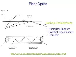
ITU Wavelength Grid • A set of standardized wavelengths based on Attenuation characteristics of fiber. • DWDM • S-Band - 1491nm to 1529nm • C-Band - 1530nm to 1569nm • L-Band - 1570nm to 1611nm • Other Ranges • 800nm - 900nm • 1250nm - 1350nm
Channel Spacing • DWDM –100Ghz (.78nm) or 50Ghz (.39nm) • CWDM – Wider spacing 2.5Thz (20nm) channel spacing from 1271nm to 1611nm CWDM 20nm Spacing DWDM 100Ghz Spacing
OSNR • OSNR – Optical Signal to Noise Ratio • The ultimate value in decibels (dB) that indicates signal quality. Higher = Better • Degrades over distance due to cumulative linear and non-linear effects • Amplification reduces • Must Regenerate when it becomes too low
Fiber - Linear Effects • Attenuation – The power level of the signal is reduced linearly over distance. • Intrinsic Causes • Fiber impurities • Material absorption • Rayleigh Scattering • Extrinsic Causes • Macrobending – Visible bend that exceeds recommended bend radius • Microbending – Usually not visible, may be temperature or stress related
Amplification • Attenuation can be corrected using amplifiers • Signal must be amplified every 70 ~ 120km • Most common EDFA amplifiers Amplify signal and noise equally which decreases OSNR value
Fiber - Linear Effects - Dispersion • Dispersion - The widening of a light pulse as it travels through fiber.
Fiber - Linear Effects - CD • Chromatic Dispersion (CD) –Each wavelength travels at a slightly different speed. • Varies by type of fiber and bit rate
Fiber - Linear Effects - CD • Effects increase with bandwidth
Dispersion Compensation • DCUs (Dispersion Compensation Units) can reduce effects. DCUs are spools of dispersion compensating fiber placed at intervals along the fiber path • Use different lengths to based on amount of dispersion to compensate • Electronic Dispersion Compensation can be done in Transponders. • Negative dispersion added when signal transmitted • Normal positive dispersion of fiber corrects
Fiber - Linear Effects - PMD • PMD – Polarization Mode Dispersion – Different polarizations (Axis) of light travel at different speeds • Caused by irregularities in the shape of the fiber. Not a perfect cylinder or a constant shape. • Varies by type of Fiber • More significant at higher transmission rates >10GE • DCUs do not address PMD. • Must Regenerate more frequently with higher PMD
Fiber Nonlinear Effects • Light in optical fiber exhibits nonlinear effects when under the influence of electrical and magnetic fields • Scattering - Photons interact with themselves and the medium they are traveling through causing scattering effects • Stimulated Raman Scattering (SRS) scatters in forward and reverse direction • Stimulated Brillouin Scattering (SBS) scatters in forward direction only • Four-Wave Mixing - 3 optical frequencies interact in a nonlinear medium giving rise to a fourth frequency.
OEO (3R) Regeneration • OSNR will continue to degrade • The optical signal will need to be converted back to an electrical/digital signal before it becomes unrecoverable. • Regenerate with back to back transponders
Additional References • http://www.iec.org/online/tutorials/light_limit/index.asp • http://www.scribd.com/doc/9038/cisco-systems-dwdm-primer-oct03
Fiber Cleaning 101 • Higher speeds less tolerant of dirty Fiber • Equipment • CLETOP • Fiber Scope • Port Swabs • Alcohol pads • NLR’s fiber cleaning procedures • Clean both front and back connectors at Patch Panels. • Use swab and aerosol to clean bulkhead connector • Dry clean fibers with CLETOP • Use scope and if still dirty use alcohol wipe • Insert in bulkhead, wait 1 min, remove & scope • Repeated as necessary
How Not to Clean Fiber • Don’t count on your telco to clean the fiber properly
The Equipment • Transponder – Converts a framed electrical signal (10GE OC192) into an optical signal at a specific wavelength. • Mux – Multiplexes multiple discrete wavelength signals into a composite signal. • DeMux – De-Multiplexes the Composite signal back into the individual wavelengths • DCU (Dispersion Compensation Unit) - Uses coils of Dispersion Compensating Fiber to reverse effects of Dispersion • Amplifiers • EDFA (Erbium Doped Fiber Amplifier) • RAMAN • Management Cards
Terminal Node • All wavelengths must drop and terminate on a TXP • Use MUX/DMX to add or drop • May continue circuit by cross-connecting to other terminal Transponder Transponder Transponder Transponder Transponder Transponder Transponder Transponder West Terminal East Terminal
Terminals … Chicago Terminals … Facing STAR Facing KANS Facing CLEV
Terminal Node CHCGIL39A
Terminal Node CHCGIL39A
OADM -Optical Add Drop Multiplexor • Selected wavelengths may drop and terminate on a TXP • Use Band Filter or ROADM to add or drop • Other circuits continue through express/pass-through Transponder Express Channel Transponder West OADM East OADM
Filters & ROADMs … • Band filters drop a specific range of wavelengths allowing the rest to pass through • ROADMs are programmable filters that allow the provisioner to choose which wavelengths drop and which pass through To STAR Terminal Chicago TerminalFacingKANS CHIC ROADM To Cleveland To Kansas
OADM Node CLEVOH39A
Can Build Complex Networks Fiber Pair Fiber Pair Fiber Pair Terminal OADM OADM OADM OADM NREN University University University
NLR CHIC-WASH • Three types of optical nodes • Single- degree ROADM (Terminal) • Multi-degree ROAMD (Add/Drop or Pass-Thru) • Amplifier
National LambdaRail SEATTLE PORTLAND BOISE BOSTON SYRACUSE CLEVELAND OGDEN CHICAGO NEW YORK DENVER PHILADELPHIA SUNNYVALE PITTSBURGH WASHINGTON SALT LAKE CITY KANSAS CITY RALEIGH RATON LOS ANGELES TULSA PHOENIX ALBUQUERQUE SAN DIEGO ATLANTA DALLAS PENSACOLA EL PASO HOUSTON JACKSONVILLE BATON ROUGE SAN ANTONIO NLR WaveNet (Layer 1), FrameNet (Layer 2) and PacketNet (Layer 3) PoP Exchange Points NLR Owned Fiber NLR WaveNet and FrameNet PoP Leased Waves NLR WaveNet PoP
NLR Layer 1 (WaveNet) Circuits that go north through Cleveland need to be regenerated SEATTLE PORTLAND Circuits that go south through Denver need to be regenerated BOISE SYRACUSE NEW YORK CHICAGO CLEVELAND PHILADELPHIA OGDEN DENVER PITTSBURGH SUNNYVALE WASHINGTON KANSAS CITY RALEIGH RATON LOS ANGELES TULSA CHARLOTTE PHOENIX ALBUQUERQUE ATLANTA SAN DIEGO DALLAS PENSACOLA EL PASO JACKSONVILLE BATON ROUGE HOUSTON SAN ANTONIO Regenerated Add/Drop
Cisco 15454 Management • Direct Access to Cisco 15454 ONS DWDM Shelf requires web browser and Java. • Java versions vary depending on version of CTC • CTC 7.0.2 uses Java 1.4.12 • CTC 8.5.1 and 9.0 use Java 1.5 or newer • GRNOC Syseng provides Windows hosts available via RDC • Individual Shelf Management • Each Shelf has own TID and IP Address • Must login to Front End Shelves individually to view Transponders • Multishelf Management • Single TID and IP Address for multiple shelf system (Node) • First Shelf is Node Controller • Additional shelves are subtended • Requires MS-ISC-100T Cards or External Switch