Download

1 / 21
210 likes | 272 Views
Attend EE 42 Lecture 4 to learn about resistors in parallel, current division, realistic models of sources, and more. Beginners welcome! Happening at 290 Cory from 10AM-4PM. Advance your knowledge in circuit analysis. Stay informed!

E N D
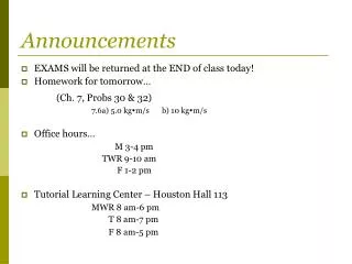
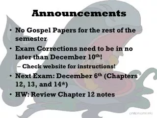
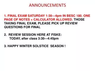
Announcements • Free, Drop-In Tutoring in 290 Cory, 10AM-4PM • Courtesy of HKN • Robotics Club Meeting • Tonight at 6pm, 306 Soda (HP Auditorium) • Find out more about current projects • Beginners welcome! EE 42 Lecture 4
Circuit Analysis Basics, Cont. • Resistors in Parallel • Current Division • Realistic Models of Sources • Making Measurements • Tips and Practice Problems EE 42 Lecture 4
Elements in Parallel • KVL tells us that any set of elements which are directly connected by wire at both ends carry the same voltage. • We say these elements are in parallel. KVL clockwise, start at top: Vb – Va = 0 Va = Vb EE 42 Lecture 4
R2 R1 R3 Elements in Parallel--Examples Which of these resistors are in parallel? R8 R4 R5 R7 R6 None R7 and R8 R4 and R5 EE 42 Lecture 4
+ VR _ R1 R3 R2 Resistors in Parallel • Resistors in parallel carry the same voltage. All of the resistors below have voltage VR . • The current flowing through each resistor could definitely be different. Even though they have the same voltage, the resistances could be different. i1 = VR / R1 i2 = VR / R2 i3 = VR / R3 i1 i2 i3 EE 42 Lecture 4
Resistors in Parallel • If we view the three resistors as one unit, with a current iTOTAL going in, and a voltage VR, this unit has the following I-V relationship: iTOTAL = i1 + i2 + i3 = VR(1/R1 + 1/R2 + 1/R3) in other words, VR = (1/R1 + 1/R2 + 1/R3)-1 iTOTAl So to the outside world, the parallel resistors look like one: iTOTAL iTOTAL + VR _ + VR _ REQ R1 R3 R2 i1 i2 i3 REQ = (1/R1 + 1/R2 + 1/R3)-1 EE 42 Lecture 4
Current Division • If we know the current flowing into two parallel resistors, we can find out how the current will divide up in one step. • The value of the current through R1 is i1 = iTOTAL R2 / (R1 + R2) • The value of the current through R2 is i2 = iTOTAL R1 / (R1 + R2) • Note that this differs slightly from the voltage division formula for series resistors. iTOTAL R1 R2 i1 i2 EE 42 Lecture 4
Current Division—Other Cases • If more than two resistors are in parallel, one can: • Find the voltage over the resistors, VR, by combining the resistors in parallel and computing VR = iTOTAL REQ. Then, use Ohm’s law to find i1 = VR / R1, etc. • Or, leave the resistor of interest alone, and combine other resistors in parallel. Use the equation for two resistors. iTOTAL iTOTAL + VR _ + VR _ R1 R3 R2 REQ i1 i2 i3 EE 42 Lecture 4
Issues with Series and Parallel Combination • Resistors in series and resistors in parallel, when considered as a group, have the same I-V relationship as a single resistor. • If the group of resistors is part of a larger circuit, the rest of the circuit cannot tell whether there are separate resistors in series (or parallel) or just one equivalent resistor. All voltages and currents outside the group are the same whether resistors are separate or combined. • Thus, when you want to find currents and voltages outside the group of resistors, it is good to use the simpler equivalent resistor. • Once you simplify the resistors down to one, you (temporarily) lose the current or voltage information for the individual resistors involved. EE 42 Lecture 4
Issues with Series and Parallel Combination • For resistors in series: • The individual resistors have the same current as the single equivalent resistor. • The voltage across the single equivalent resistor is the sum of the voltages across the individual resistors. • Individual voltages and currents can be recovered using Ohm’s law or voltage division. i i REQ R1 R2 R3 v - + + v - EE 42 Lecture 4
Issues with Series and Parallel Combination • For resistors in parallel: • The individual resistors have the same voltage as the single equivalent resistor. • The current through the equivalent resistor is the sum of the currents through the individual resistors. • Individual voltages and currents can be recovered using Ohm’s law or current division. iTOTAL iTOTAL + VR _ + VR _ R1 R3 R2 REQ i1 i2 i3 EE 42 Lecture 4
Approximating Resistor Combination • Suppose we have two resistances, RSM and RLG, where RLG is much larger than RSM. Then: ≈ RSM RLG RLG ≈ RSM RLG RSM EE 42 Lecture 4
Ideal Voltage Source • The ideal voltage source explicitly defines the voltage between its terminals. • The ideal voltage source could have any amount of current flowing through it—even a really large amount of current. • This would result in high power generation or absorption (remember P=vi), which is unrealistic. Vs EE 42 Lecture 4
RS Vs Realistic Voltage Source • A real-life voltage source, like a battery or the function generator in lab, cannot sustain a very high current. Either a fuse blows to shut off the device, or something melts… • Additionally, the voltage output of a realistic source is not constant. The voltage decreases slightly as the current increases. • We usually model realistic sources considering the second of these two phenomena. A realistic source is modeled by an ideal voltage source in series with an “internal resistance”. EE 42 Lecture 4
Realistic Current Source • Constant-current sources are much less common than voltage sources. • There are a variety of circuits that can produces constant currents, and these circuits are usually composed of transistors. • Analogous to realistic voltage sources, the current output of the realistic constant currents source does depend on the voltage. We may investigate this dependence further when we study transistors. EE 42 Lecture 4
Taking Measurements • To measure voltage, we use a two-terminal device called a voltmeter. • To measure current, we use a two-terminal device called a ammeter. • To measure resistance, we use a two-terminal device called a ohmmeter. • A multimeter can be setup to function as any of these three devices. • In lab, you use a DMM to take measurements, which is short for digital multimeter . EE 42 Lecture 4
Measuring Current • To measure current, insert the measuring instrument in serieswith the device you are measuring. That is, put your measuring instrument in the path of the current flow. • The measuring device will contribute a very small resistance (like wire) when used as an ammeter. • It usually does not introduce serious error into your measurement, unless the circuit resistance is small. i DMM EE 42 Lecture 4
Measuring Voltage • To measure voltage, insert the measuring instrument in parallelwith the device you are measuring. That is, put your measuring instrument across the measured voltage. • The measuring device will contribute a very large resistance (like air) when used as a voltmeter. • It usually does not introduce serious error into your measurement unless the circuit resistance is large. DMM + v - EE 42 Lecture 4
Measuring Resistance • To measure resistance, insert the measuring instrument in parallelwith the resistor you are measuring with nothing else attached. • The measuring device applies a voltage to the resistance and measures the current, then uses Ohm’s law to determine resistance. • It is important to adjust the settings of the meter for the approximate size (Ω or MΩ) of the resistance being measured so appropriate voltage is applied to get a reasonable current. DMM EE 42 Lecture 4
Example • For the above circuit, what is i1? • Suppose i1 was measured using an ammeter with internal resistance 1 Ω. What would the meter read? 9 Ω 27 Ω 54 Ω 3 A i1 i2 i3 EE 42 Lecture 4
9 Ω 27 Ω 54 Ω 3 A i1 i2 i3 9 Ω 18 Ω 3 A i1 Example • By current division, i1 = -3 A (18 Ω)/(9 Ω+18 Ω) = -2 A • When the ammeter is placed in series with the 9 Ω, • Now, i1 = -3 A (18 Ω)/(10 Ω+18 Ω) = -1.93 A 1 Ω 10 Ω 27 Ω 54 Ω 3 A 18 Ω 3 A 9 Ω i1 i2 i1 i3 EE 42 Lecture 4