Download
1 / 24
240 likes | 420 Views
IFE Plant Structural Concepts Including Shielding and Optical Stability Requirements. Thomas Kozub, Charles Gentile, Irving Zatz - PPPL. Overview. Conceptual Development of an Integrated IFE Facility Structural Design Incorporates Several Interconnected Design Requirements:

E N D
IFE Plant Structural Concepts Including Shielding and Optical Stability Requirements Thomas Kozub, Charles Gentile, Irving Zatz - PPPL
Overview • Conceptual Development of an Integrated IFE Facility Structural Design • Incorporates Several Interconnected Design Requirements: • Basic Structure for Facility Core • Provide Stable Platform for Optics • Provide Necessary Shielding • Incorporate Methods for Plant Servicing • Meet all Regulatory Requirements • All Elements are Integrated into an Single Efficient Design
Generic Structural Design • Major facility dimensions are fixed as determined by optical geometry and shielding requirements • Any reactor chamber core design that fits within the 40m diameter bio-shield can be accommodated with this design • Integrated multifunctional use of components to efficiently meet multiple requirements
Fundamental Design • The basic design is very simple, a combination of spheres and cylinders. The inner most concrete structural component is the spherical “bio-shield” which contains and supports the reaction chamber and all associated components. The bio-shield is contained within a larger structural sphere composed of the interconnected GIMM outer supports struts and connected to the bio-shield through the GIMM shielding units. This spherical GIMM shield support structure is integrated into a series of cylinders carrying the load to the foundation. These cylinders are interlinked with radial arches.
Fundamental Design • For the tulip magnetic intervention concept, the suggested vessel chamber is a cylinder with hemispherical ends. This geometry will contain all necessary core components while minimizing vacuum volume and will fit completely through the service opening.
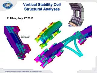
Analysis Methodology • Optimize the static structural design to withstand dead loads and mechanical loads. • Perform a modal and, if necessary, a frequency and transient analysis to determine the structural adequacy of the design subjected to dynamic loads. • If necessary, optimize the design of GIMM and other relevant components to assure performance will be within the specified displacement and vibration criteria. • Optimize material utilization and function.
Optical Platform Stability • Design Requirements: • Static support of the GIMM structures to the facility's foundation. • Structural elements to maintain stability and alignment within the prescribed tolerances of the optical components. • A GIMM base that provides a mirror surface flatness to a quarter wavelength. • Elimination of high frequency vibration at GIMM that is beyond the dynamic tracking response of the steering mirrors. • Methods for mounting the GIMM within the vacuum beam duct at the several various required orientations. • Necessary features for the installation, adjustment, servicing and replacement of the GIMM components.
Drawing by Malcolm McGeoch Current GIMM Geometry
GIMM Shield Units form an Integrated Structural Component of the Facility Providing the Dual Functions of Load carrying structure and shielding
Sources of Vibration • Reducing the sources of vibration to an minimum is as important as the attenuation of vibration. • Sources of vibration grouped by strength of coupling to the GIMM: • Sources acting directly on the GIMM. • IFE Process sources acting on the central core structure. • Facility and other sources dispersed throughout the plant.
Sources of Vibration Acting Directly on the GIMM • Thermal shock from target detonation • Impulse at rate ~5Hz • Thermal shock from laser pulse • Impulse at rate ~5Hz • Flow of GIMM coolant • Continuous source • Electromagnetic effects • To be determined
IFE Process Sources of Vibration Through the Facility Structure • Target detonation impulse • Ion, radiation and thermal impulse at ~5Hz • Magnetic Intervention field pulse • Field force response into structure at ~5Hz
Facility and Other Sources of Vibration • Rotating machinery: pumps, motors, etc. • Valves operating • Fluid flow through pipes • Transformers and other electrical devices • Elevators, cranes, trucks, doors • External sources through foundation • Atmospheric and Seismic
Primary Servicing Design • Dome incorporates a large crane with a 1500 ton capacity (Typical “ship yard” type) • Upper level platform for locating large service components of up to 1500 ton each • Upper four GIMM shield units are removable • Bio-Shield incorporates a 22m removable plug for vessel access
Example illustrations with and withoutremovable core components
Major Service Loads(Current MI Design) • Mirror Shield Unit 1200 ton • Bio-Shield Plug 1100 ton • Vessel Dome 500 ton • Vessel Cylinder 1000 ton • MI Core Components <500 ton each
Conclusions • This design strategy provides a scalable and flexible approach to meeting the structural requirements of an evolving project. • This design efficiently incorporates the required shielding materials into the core structure providing increased stability and functionality • This design rigidly binds together critical components and infrastructure while minimizing the effects vibration.
Future work • Complete static load and vibration mode finite element analysis • Optimization and volume reduction of structural elements • GIMM mounting: • Vibration isolator design • Refinement of the GIMM shield units • Cooling methods minimizing vibration • Servicing features and details • Integrated facility structural details