Download
1 / 61
630 likes | 849 Views
Smooth Spline Surfaces over Irregular Topology. Hui-xia Xu Wednesday, Apr. 4, 2007. Background. limitation an inability of coping with surfaces of irregular topology, i.e., requiring the control meshes to form a regular quadrilateral structure. Improved Methods.

E N D
Smooth Spline Surfaces over Irregular Topology Hui-xia Xu Wednesday, Apr. 4, 2007
Background • limitation • an inability of coping with surfaces of irregular topology, i.e., requiring the control meshes to form a regular quadrilateral structure
Improved Methods • To overcome this limitation, a number of methods have been proposed. Roughly speaking, these methods are categorized into two groups: • Subdivision surfaces • Spline surfaces
Subdivision Surfaces---main idea iteratively applying resultant mesh converging to smooth surface polygon mesh refinement procedure
Subdivision Surfaces---magnum opus • Catmull-Clark surfaces • E Catmull and J Clark. Recursively generated B-spline surfaces on arbitrary topological meshes, Computer Aided Design 10(1978) 350-355. • Doo-Sabin surfaces • D Doo and M Sabin. Behaviour of recursive division surfaces near extraordinary points, Computer Aided Design 10 (1978) 356-360.
About Subdivision Surfaces • advantage • simplicity and intuitive corner cutting interpretation • shortage • The subdivision surfaces do not admit a closed analytical expression
Method 1 • the technology of manifolds • C Grimm and J Huges. Modeling surfaces of arbitrary topology using manifolds, Proceedings of SIGGRAPH (1995) 359-368 • J Cotrina Navau and N Pla Garcia. Modeling surfaces from meshes of arbitrary topology, Computer Aided Geometric Design 17(2000) 643-671
Method 2 • isolate irregular points • C Loop and T DeRose. Generalised B-spline surfaces of arbitrary topology, Proceedings of SIGGRAPH (1990) 347-356 • J Peters. Biquartic C1-surface splines over irregular meshes, Computer-Aided Design 12(1995) 895-903 • J J Zheng et al. Smooth spline surface generation over meshes of irregular topology, Visual Computer(2005) 858-864 • J J Zheng et al. C2 continuous spline surfaces over Catmull-Clark meshes, Lecture Notes in Computer Science 3482(2005) 1003-1012 • J J Zheng and J J Zhang. Interactive deformation of irregular surface models, Lecture Notes in Computer Science 2330(2002) 239-248 • etc.
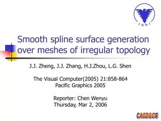
Smooth Spline Surface Generation over Meshes of Irregular Topology J J Zheng , J J Zhang, H J Zhou and L G Shen Visual Computer 21(2005), 858-864
What to Do • In this paper, an efficient method generates a generalized bi-quadratic B-spline surface and achieves C1 smoothness.
Zheng-Ball Patch • A Zheng-Ball patch is a generation of a Sabin patch that is valid for 3- or 5-sided areas. For more details, the following can be referred: • J J Zheng and A A Ball. Control point surface over non-four sided areas, Computer Aided Geometric Design 14(1997)807-820. • M A Sabin. Non-rectangular surfaces suitable for inclusion in a B-spline surface, Hagen, T. (ed.) Eurographics (1983) 57-69.
Zheng-Ball Patch • An n-sided Zheng-Ball patch of degree m is defined by the following : This patch model is able to smoothly blend the surrounding regular patches
Zheng-Ball Patch • : the n-ple subscripts, • :n parameters of which only two are independent • : denotes the control points in ,as shown in Fig 1. • : the associated basis functions
Fig 1. Control points for a six-sided quadratic Zheng-Ball patch
Spline Surface Generation---irregular closed mesh • Generate a new refined mesh • carry out a single Catmull-Clark subdivision over the user-defined irregular mesh • Construct a C1 smooth spline surface • regular vertex---a bi-quadratic Bézier patch • Otherwise---a quadratic Zheng-Ball patch
Related Terms • Valence • The valence of a point is the number of its incident edges. • Regular vertex • If its valence is 4, the vertex is said to be regular. • Regular face • A face is said to be regular if none of its vertices are irregular vertices.
Catmull-Clark Surfaces---subdivision rules • Generation of geometric points • Construction of topology
Geometric Points • new face points • averaging of the surrounding vertices of the corresponding surface • new edge points • averaging of the two vertices on the corresponding edge and the new face points on the two faces adjacent to the edge • new vertex points • averaging of the corresponding vertices and surrounding vertices
Topology • connect each new face point to the new edge points surrounding it • Connect each new vertex point to the new edge points surrounding it
Mesh Subdivision Fig 2. Applying Catmull-Clark subdivision once to vertex V with valence n
Mesh Subdivision • new faces: four-sided • The valence of a new edge point is 4 • The valence of the new vertex point v remains n • The valence of a new face point is the number of edges of the corresponding face of the initial mesh
Patch Generation • For a regular vertex, a bi-quadratic Bézier patch is used • For an extraordinary vertex, an n-sided quadratic Zheng-Ball patch will be generated
Overall C1 Continuity Fig 3. Two adjacent patches joined with C1 continuity
Geometric Model Fig 4. Closed irregular mesh and the resulting geometric model
Spline Surface Generation---irregular open mesh • Step 1: subdividing the mesh to make all faces four-sided • Step 2: constructing a surface patch corresponding to each vertex • The main task is to deal with the mesh boundaries
Boundary mesh subdivision for 2- and 3-valent vertices • face point: Centroid of the i-th face incident to V • edge point: averaging of the two endpoints in the associated edge • vertex point: equivalent to n-valent vertex V of the initial mesh
Illustration Fig 5. Subdivision around a boundary vertex v (n=3)
Boundary mesh subdivision for valence>3 • For each vertex V of valence>3, n new vertices Wi (i=1,2, …,n) are created by
Convex Boundary Vertex Fig 6. Left: Convex boundary vertex V0 of valence 4. Right: New boundary vertices V0 , W1 and W4 of valence 2 or 3
Concave Boundary Vertex Fig 7. Left: Concave inner boundary vertex V of valence 4. Right: New boundary vertices W1 and W4 of valence 3
Some Definitions • Boundary vertex: vertex on the boundary of the new mesh • Boundary face: at lease one of its vertices is a boundary vertex • Intermediate vertex: not a boundary vertex, but at least one of its surrounding faces is a boundary face • Inner vertex: none of the faces surrounding is a boundary face
Generation Rules--- intermediate vertex • d is a central control point • d2i is a corner point if its valence is 2 • d2i-1 is a mid-edge control point if its valence is 3 • ½*(di + di+1 ) is a corner control point if the valences of di and di+1 are 3. • ½*(d2i-1 + d) and ½*(d2i+1 + d) are the two mid-edge control points if fi is not a boundary face. • The centroid of face fi is a corner point if fi is not a boundary face.
Generation Rules--- intermediate vertex Fig 8. Intermediate vertex d (valence 5). Control points (○) for the patch corresponding to it
Geometric Model Fig 9. Two models generated from open meshes by proposed method
Conclusions Fig 10. Sphere produced with Loop’s method (left ) and with the proposed method (right )
Interactive Deformation of Irregular Surface Models J J Zheng and J J Zhang LNCS 2330(2002), 239-248
Background • Interactive deformation of surface models is an important research topic in surface modeling. • However, the presence of irregular surface patches has posed a difficulty in surface deformation.
Background • Interactive deformation involves possibly the following user-controlled deformation operations • moving control points of a patch • specifying geometric constraints for a patch • deforming a patch by exerting virtual forces • By far the most difficult task is to all these operations without violating their connection smoothness
Outline of the Proposed Research • This paper will concentrate on two issues • modeling of irregular surface patches • Zheng-Ball model • the connection between different patches • formulate an explicit formula to degree elevation and to insert a necessary number of extra control points
Zheng-Ball Patch • This patch model can have any number of sides and is able to smoothly blend the surrounding regular patches • This surface model is control-point based and to a large extent similar to Bézier surfaces
Zheng-Ball Patch Fig 11. 3-sided cubic Zheng-Ball Patch with its control points
Explicit Formula of Degree Elevation (m=3) explicit formula
Explicit Formula of Degree Elevation • The functions are defined by • The functions are defined by
After Degree Elevation Fig 12. Quartic patches with control points after degree elevation. The circles represent the control points contributing to the C0 condition, the black dots represent the control points contributing G1 condition, and the square in the middle represents the free central control point
Central Control Point • The central control point has provided an extra degree of freedom. • Moving this control point will deform the shape of the blending patch intuitively, without violating the continuity conditions
Energy function • For an arbitrary patch , an energy function is defined by : where Vi, Ki and Fi are the control point vector, stiffness matrix and force vector, respectively.