Download
1 / 52
520 likes | 530 Views
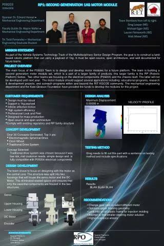
This project aims to design and build a modular motor module for the RP1 platform, with a focus on robustness and wireless communication. The project involves the design of the drivetrain, steering, and yoke subsystems, as well as the platform for mounting the motor module. Challenges include friction losses, belt tensioning, and machining tolerances.

E N D
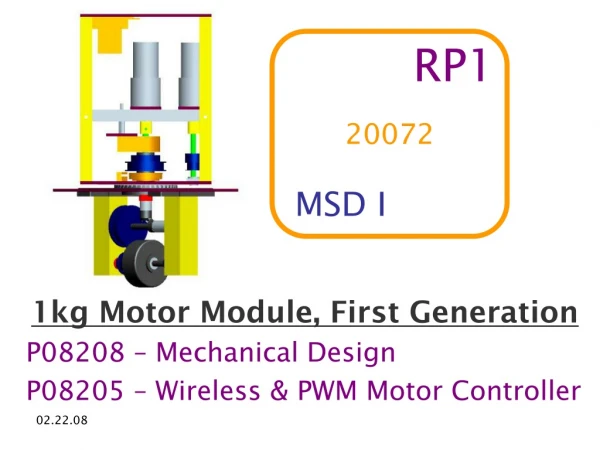
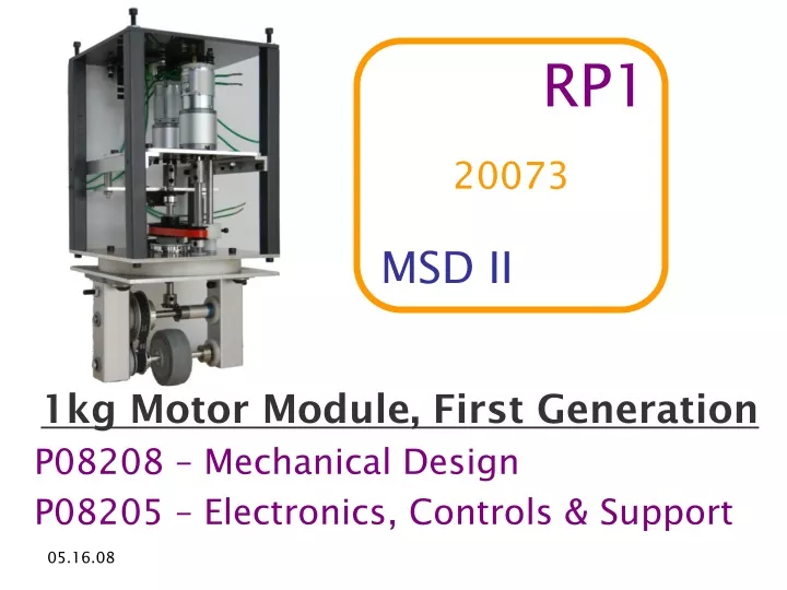
20073 RP1 MSD II 1kg Motor Module, First Generation P08208 – Mechanical Design P08205 – Electronics, Controls & Support
WHAT IS A MOTOR MODULE ? aka “MM” MODULAR MOUNTING STEER DRIVE
100kg 10kg 1kg OFF THE SHELF MOTOR MODULES
RP100( Wired ) RP10( Wired ) Sister projects! RP1( Wireless ) RP10( Redesign )
Autonomous! RP10Redesign Smaller! Lighter! Wireless! Robust!
FORMAT Overview Project Specifications System Level Subsystem Contributions 208: Drive / Steer / Yoke 205: Support / Electronics / Controls Closing Comments Results Strengths & Weaknesses Future of RP1
Mechanical DESIGN Overview Drive Train Upper Yoke Steering Lower Yoke
ELECTRONICS & CONTROLS OVERVIEW PWM Motor Controller Computer Circuit Board Wireless Transceivers Microprocessor RP1 Motor Module
CRITICAL REQUIREMENTS • Transport 1kg Payload • Robust = Withstand Tabletop Drop • Wireless Communication • Power Motors with a PWM Signal • Open Source & Open Architecture • Reflect Design of the RP Family • Modular Design for Multiple End Uses
Quantity 1, Functioning Platform & Motor Module 3, Motor Modules Speed @ max efficiency 38 in/s Drop Test Repair Time < 20 min Battery Life 1 hour + Modular Design EXPECTATIONS 1 2 3
Responsibilities: Design modular drivetrain system Multiple modes of motor operation Design and build a robust drivetrain Challenges of MSD II Drivetrain friction losses The need for a belt tensioner? Machining knowledge inadequacy Failing drop testing Unforeseen assembly woes Differences between analytical solutions and testing results Drivetrain Subsystem 05.16.08
Gearbox Selection Process • Similarly a motor gearbox can be selected for max motor power 05.16.08 Using the chart to the left a motor gearbox can be selected from velocity requirements that ensures efficient motor operation
Final Drivetrain Design IG-32GM 24V Motor 27:1 gearbox reduction Steel couples with setscrews Stainless steel drive axles Steel miter gears Aluminum spacers with thrust bearings 1:2 synchronous drive pulley Aluminum axle with keyway for wheel 05.16.08
Strengths & Weaknesses Strengths Modular gearbox options Multiple opportunities to change gear ratios Belt protects critical drive components Easy assembly of drive components Weaknesses Lack of belt tensioner limits modularity Size of motor increases RP1 size Limited availability of motor gearboxes 05.16.08
STEERING SUBSYSTEM • Responsibilities: • Design a steering system capable of infinite rotation • Implement, build and integrate with all RP1 subsystems • Challenges of MSD II • Total re-design including custom turntable, starting week #1 • Also incorporated re-vamp of tensioning system • Subsystem integration • Belt Sizing • Friction!
It’s Alive! 05.16.08
Strengths: Robust steer system Custom turntable is light, smooth, and easy to access/assemble Infinite rotation Intuitive and efficient belt tensioning Weaknesses Side load from belt drive system causing misalignment Extreme sensitivity to belt length Tendency of steer system to force rotation of drive shaft, and vice versa Friction! Demands tight tolerances Strengths & Weaknesses ü ü ü ü L L L L L L L
DRIVE & STEERING Q & A
YOKE SUBSYSTEM 05.16.08
YOKE SUBSYSTEM Responsibilities: • Responsible for structural skeleton of RP1 • Design a rigid and robust framework • House all other sub-systems within framing • Provide protection against a drop to the floor Challenges of MSD II: • Maintaining machining tolerances during mass production • Lack of experience with machining equipment early in MSDII • Developing precise and efficient machining techniques
Drop Test on Side 05.16.08
Damage to Axle 05.16.08
Strengths Robust: designed for impact Concentrates force of impact from drop in lower axle Easily assembled and disassembled Weaknesses Size: minimally smaller than RP10 Lower axle fails in drop test but can be quickly replaced Strengths & Weaknesses
Responsibilities: Design a prototype platform Includes area for 1kg payload Includes area for platform electronics Testing the functionality of 1 MM at a time Built-in wheels to allow for platform travel Design a modular mounting system Must be capable of attachment to platform Must meet design spec for attachment Challenges of MSD II Use of materials readily available for platform Having a low center of mass for drivability PLATFORM 05.16.08
PLATFORM EFFORTS Mounting Time: 50 sec 05.16.08
STRENGTHS & WEAKNESSES Strengths Easy to make prototype platform Very quick and efficient mounting Weaknesses Made of plywood and boards Structural support questionable when using substantial weight Requires a square-shaped cut-out MM must mount in the designated forward direction for index to work properly 05.16.08
YOKE & PLATFORM Q & A
Responsibilities Provide components for motor control H-bridge Boost & Buck PCB Interface PCB Wiring & Connectors Design and implement power supply Challenges of MSD II PCB board design Integration of all electrical components Electronics 05.16.08
Electronics 05.16.08
Electronics 05.16.08
Printed Circuit Boards 05.16.08
PCB Build 05.16.08
Strengths Capacity for 2 MM’s Integration of all electrical components Single connection with platform Weaknesses Takes time to locate broken components on PCB PCB Corrections PCB has no output diode Reflections 05.16.08
Controls • Responsibilities: • GUI for user control • Wireless communication between MM and computer • Generate all necessary signals used for controlling motors • Display speed, turning angle, and battery life • Challenges of MSD II • Selected wireless components not functioning • Limitations of microprocessor – not enough I/O pins • Out of practice with Java
Implementation • Wireless Transmission: • Couldn’t download code to MICAZ motes • TelosB motes used instead • Not yet demonstrated to be functional • Microprocessor: • Freescale • Handles encoder feedback • Speed up, slow down, turn left and right • GUI: • Java, using the Eclipse IDE • New design in consultation with Prof. Hawker
Strengths Ability to turn, drive, and stop based on commands issued by the user GUI supports multiple platform designs Open-source, Java readily available Weaknesses One direction communication with the MM Only set up to work with one MM Strengths & Weaknesses
CONTROLS & ELECTRONICS Q & A
RESULTS • MM attaches in under 1 minute • Weighs under 5 pounds • Complete disassembly in less than 10 minutes • Compact size • Infinite rotation • Robust • Less than $900
COST 05.16.08
The Future of RP1 2 3 1 French Collaboration with INSA Software Engineering Senior Design DPM Students Senior Design for EE & CE’s
COULD RP1 HANDLE 10Kg? • Proven robust design • Modular mounting • Replace drive with 1:71 gearbox motor • Resulting 14.5 in/s @ peak efficiency • ANSYS MODELING RESULTS Check: • Design of Machine Element calculations • Effects on batteries
COULD RP1 HANDLE 10Kg? Yes it can! 22.5 lb Payload! (10.2 kg) 05.16.08
REFLECTIONS Strengths Weaknesses Oversized Failed to implement wireless communication Processor can only handle 1 MM of feedback PCB corrections were necessary • Robust motor module • Demonstrated modular design • Easy to connect • Controllable turn/drive/stop/align
THREE SIMPLIFICATIONS • Open motor selection & configuration • 170°or 180° rotation requirement, to replace infinite rotation requirement • Emphasize compact design + Establish clear size constraints + Goal of existing design size (ex. 10%)
That’s It Folks! Q & A
Gearbox Selection Process 05.16.08
Gearbox Selection Process 05.16.08