Download
1 / 27
270 likes | 441 Views
DDS design status . Alessandro D’Elia. Outline. General overview of DDS working principle CLIC_DDS_A design status Towards CLIC_DDS_B: wakefield simulations and impedances HOM coupler design Some conclusion. Damped and detuned design.

E N D
DDS design status Alessandro D’Elia
Outline • General overview of DDS working principle • CLIC_DDS_A design status • Towards CLIC_DDS_B: • wakefield simulations and impedances • HOM coupler design • Some conclusion
Damped and detuned design • Detuning: A smooth variation in the iris radii spreads the dipole frequencies. This spread does not allow wake to add in phase • Error function distribution to the iris radii variation results in a rapid decay of wakefield. • Due to limited number of cells in a structure (truncated Gaussian) wakefieldrecoheres. • Damping: The recoherence of the wakefield is suppressed by means of a damping waveguide like structure (manifold). • Interleaving neighbouring structure frequencies help enhance the wake suppression
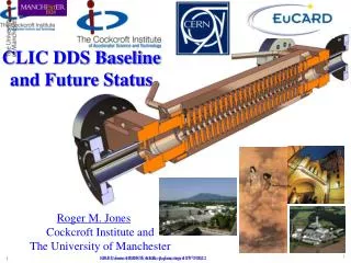
Acceleration cells Beam tube Manifold HOM coupler High power rf coupler NLC/GLC DDS design Ref: R. Jones, et al. , PRSTAB 9, 102001, (2006).
Large bandwidth structure Error function distribution Courtesy of R. M. Jones
Interleaving Courtesy of V. Khan
Why a Detuning Damping Structure (DDS) for CLIC • Huge reduction of the absorbing loads: just 4x2 loads per structure • Inbuilt Wakefield Monitors, Beam Position Monitors that can be used as remote measurements of cell alignments • In principle, lower pulse temperature rise • Consequently (still in principle) lower probability of breakdown events • Huge reduction of the outer diameter of the machined disks
CLIC_DDS_A • In October 2009 it has been decided to produce a first prototype to be tested at input power of 62 MW to ascertain the suitability of the structure to sustain high e.m. field gradients • RF and mechanical design completed in Summer 2010 • 4 qualification disks machined by VDL received in Oct 2010 • The 4 disks have been successfully bonded by Bodycote • The whole structure will be machined in Japan by Morikawa under the supervision of KEK • High Power Tests are foreseen as soon as we will get the full structure NOW
CLIC_DDS_A: regular cell optimization The chose of the cell geometry is crucial to meet at the same time: Wakefield suppression Surface fields in the specs DDS1_C DDS2_E Consequences on wake function Cell shape optimization for fields
CLIC_DDS_A: regular cells, final design Roundings enhance the magnetic field however a reduction of the slot size mitigates this enhancement and RF parameters are back within required limits. Also the wake damping is still in the limits with margins for a further improvement. • Further information: • Manifold dimensions are uniform throughout the structure • The manifold radius is now parameterised in order to keep the lowest manifold mode above 12 GHz.
CLIC_DDS_A some further detail VDL BODYCOTE
CLIC_DDS_B • The study of a further structure (CLIC_DDS_B) is already started • This structure will be based on CLIC_DDS_A but will be provided with HOM couplers and with a compact coupler for fundamental mode • Both wakefield suppression and high power performances will be tested Next future
First steps toward CLIC_DDS_B Wakefield calculations for DDS are, in the early design stage, based on single infinitely periodic cells. Though cell-to-cell interaction is taken into account to calculate the wakefields, it is important to study full structure properties using computational tools.
Recalculation of Kicks and Q’s from the impedance Lorentzian fit of the peaks Procedure Qdip Kick factor
A possible geometry for the HOM Coupler • J. W. Wang and al. “Progress toward NLC/JLC prototype accelerator structure”, LINAC04 Port2 Port1 Port4 Port3 SLAC PEC PML As a first approach I decided to reproduce the same as done at for NLC/JLC: HOM coupler attached at first and last regular cells Only Matching cells uncoupled How much is the bandwidth?
A first naÏf consideration CLIC_DDS_A Impedance
Build up of the wake signal W0(t) …. Wn(t+nt) Obviously this analysis is qualitative and in the build up we are neglecting the effect of the bunches on the following ones
Some example Nb=1 Nb=10 Nb=28 Nb=100 Nb=260 Nb=312
Nb=312 “Built wake” Bunch train
Preliminary HOM coupler thoughts My understanding is that, for first dipole band the most dangerous frequency is ~18GHz. Then I’m trying to match the HOM coupler at this frequency. Same technique as for matching cells No common minima yet @ 18GHz
Conclusions • A first prototype, CLIC_DDS_A, has been fully designed and is going to be produced (hopefully at the end of the year) • The study for the HOM coupler which is the fundamental device for CLIC_DDS_B has started • New ideas to improve DDS performances are under investigation