Download
1 / 24
240 likes | 387 Views
Compton based Polarized Positrons Source for ILC. V. Yakimenko, I. Pogorelsky BNL Collaboration meeting, Beijing, January 29-February1, 2006. Outline:. Numbers and issues. Target and conversion efficiency Laser test: Laser spot size First results from laser cavity tests Plans.

E N D
Compton based Polarized Positrons Source for ILC V. Yakimenko, I. Pogorelsky BNL Collaboration meeting, Beijing, January 29-February1, 2006
Outline: • Numbers and issues. • Target and conversion efficiency • Laser test: • Laser spot size • First results from laser cavity tests • Plans
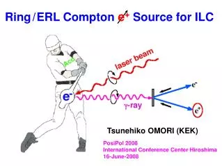
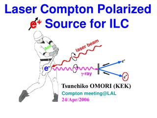
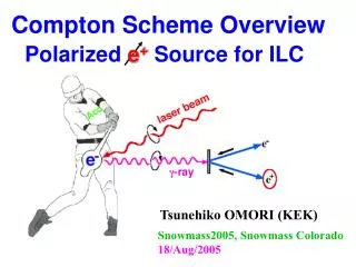
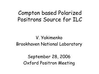
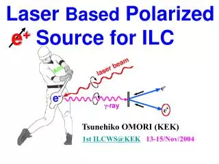
Polarized Positrons Source (PPS for ILC) Conventional Non-Polarized Positrons: In the proposal • Polarized g-ray beam is generated in Compton backscattering inside optical cavity of CO2 laser beam and 6 GeV e-beam produced by linac. • The required intensities of polarized positrons are obtained due to 10 times increase of the “drive” e-beam charge (compared to non polarized case) and 5 to 10 consecutive IPs. • Laser system relies on commercially available lasers but need R&D on a new mode of operation. • 5ps, 10J CO2 laser is operated at BNL/ATF. g to e+ conv. target 6GeV 1A e- beam 60MeV g beam 30MeV e+ beam 5-ps, 1-J CO2 laser ~2 m
Linac Compton Source (LCS): Numbers Proposal numbers are in black, Optimistic numbers are in Red
Compton Experiment at Brookhaven ATF(record number of X-rays with 10 mm laser) • More than 108 of x-rays were generated in the experiment NX/Ne-~0.35. • 0.35 was limited by laser/electron beams diagnostics • Interaction point with high power laser focus of ~30mm was tested. • Nonlinear limit (more then one laser photon scattered from electron) was verified. PRL 2005. Real CCD images Nonlinear and linear x-rays
LCS: Issues to be checked • Conversion target and capture efficiency optimization (nearly done) • Laser beam generation and injection into the cavity (very encouraging first results) • Laser cavity detailed design and tests at low and nominal repetition rate (no funding yet) • Electron beam source and IPs optics (ongoing at BNL for different project) • Cost and reliability
LCS: Conversion target and capture efficiency optimization • The proposal relies on 2% conversion efficiency of the g beam (produced in the Compton backscattering) into captured polarized positrons. • Approximate analytical model developed for quick parameter optimization predicts up to 4% efficiency. • Detailed computer simulation at ANL confirmed 2% parameter set efficiency. • Further work is needed to confirm a case with sicker target and 4% efficiency.
LCS: Conversion target and capture layout • Target: Ti - 0.3 rl • AMD: 60 cm long 10T to 2T AMD pulsed • Linac: Pulsed L-band with 30MV/m • 2% gamma to captured e+ beam efficiency predicted by analytical model and detailed computer modeling with ~70% (?) polarization Target Pre-accelerator and solenoid Photon collimator AMD
Step1. Energy filtering of the gamma beam • ~50% of the gammas with energies 30-60MeV can be selected by collimator with gq~1. Energy cross-section (top) and angular dependence (bottom) for the Compton backscattering
Step2: Gamma to pair conversion in target • ~30% of the 30-60 MeV gammas will generate e+e- pair in X/3 target. • ~25% of them will have combined energy in the 30-60 MeV range. Differential cross-section of the pair production as a function of positron energy
Step 3: Positron energy selection • ~50% of the positrons will have 30-60MeV energies. • They will loose ~15% of energy in X/3 target on average due to bremsstralung. • New energy range 25-60MeV. • Total efficiency up to this point: 50% x 30 % x 25% x 50 % = 2%. • Computer simulations predict ~2.2%.
Step 4: Capturing efficiency • All positrons in with the 25-60MeV energies can be captured. Angular acceptance is shown on the left and longitudinal phase slippage is shown on the right graphs
Step 5: Polarization • The positron longitudinal polarization goes from 0.5 at half the gamma energy to 1 at the full gamma energy for polarized gammas. Integrating from positron energy 50% to 100% of the gamma energy gives a polarization of about 0.8.
200ps CO2 oscillator 150ns 1mJ 5ps Ge 10mJ 5ps from YAG laser PC TFP PC 10mJ 5ps 300mJ 5 ps 2x30mJ 1J IP#1 IP#5 e- LCS: CO2 laser system • pulse length 5 ps • energy per pulse 1 J • period inside pulse train 12 ns • total train duration 1.5 s • train repetition rate 150 Hz
LCS:LDRD support at BNL • LDRD at the level of $110K supports this effort • Cavity simulations and tests, injection design are the main goals of the LDRD • Available at BNL/ATF CO2 Laser hardware is used to supports this effort. • PostDoc with CO2 laser experience will be soon hired to work on this project. • Funding is nearly sufficient to complete the main LDRD goals on a two-year scale.
LCS:Laser focus characterization • High power (~3J, 5ps) CO2 laser spot size of s=32mm was demonstrated using F#~4 parabola with a hole for e-beam transmission. • Proposal assumes s=40mm. • Laser is circular polarized as is required for ILC. Gaussian approximation Transmitted energy mm 75 mm 75 mm 100 mm 150 mm d=75 mm 100 mm 150 mm no pinhole
Has a potential to increase average intra-cavity power ~100 times at 10.6 microns. Purpose of the test: Demonstration of 100-pulse train inside regenerative amplifier that incorporates Compton interaction point. Demonstration of linear-to-circular polarization inversion inside the laser cavity. Test of the high power injection scheme LDRD – cavity tests
“~100 times increase of the average intra-cavity power at 10 mm” • The required laser train format / repetition rate /average acting power at each IP: 100 pulses x 150Hz x 1J = 15 kW. • Efficient interaction with electron beam requires short (~5ps) and powerful (~1-2J) laser beam. • Such high-pressure laser does not exist. Non-destructive feature of Compton scattering allows putting interaction point inside laser cavity. • We can keep and repetitively utilize a circulating laser pulse inside a cavity until nominal laser power is spent into mirror/windows losses. • Assuming available 0.5 kW CO2 laser and 3% round-trip loss, 1-J pulse is maintained over 15,000 round trips/interactions (100 pulses x 150 Hz). Thus, 0.5 kW laser effectively acts as a 15 kW laser. • Equivalent solid state ( 1mm) laser producing the same number of gamma photons should be 150 kW average power with ~10J, 5ps beam.
LCS LDRD: Simplified test setup First observations: • Optical gain over 4 ms • Misbalanced gain/loss regime results in lasing interruption by plasma • Single seed pulse amplification continues to the end
LCS LDRD: Simplified test setup • Balancing gain/losses and plasma threshold results in continuous amplification with two characteristic time constants : • ~200 ns due to CO2 inversion depletion • ~2 ms due to N2-CO2 collisional transfer. • Early injection of seed pulse before the gain reaches maximum allows to control train envelope
The best train uniformity achieved • Very encouraging results obtained with simplified cavity test setup: ~200 ps pulse of the order of 100 mJ circulated for >1 ms. • Further test would require pulse length monitoring and high pressure or isotope mixture based amplifier (to sustain 5 ps beams). 3% over 1 ms
LCS: Laser cavity detailed design and tests at low and nominal repetition rate • The key point – not funded • There is a detailed $250K/2 year proposal from SDI to study amplifier for the cavity at 5 Hz ($100K laser + modifications & R&D ~ $150K) • Not modified 150Hz laser price is ~ $450K • 1 additional FTE at BNL is needed to support amplifier work and to design, simulate and test laser cavity • ~$350K/year – 3 years is needed to test laser cavity at 5 Hz
LCS: Electron beam source and IPs optics • Photoinjector gun is simulated at CAD/BNL with the required beam parameters • Detailed design is needed and estimated 1FTE-year is expected • Depend on the number of laser IPs. Design uses 10 IPS. (potentially can be reduced to 3-5 IPs) • Should be delayed till laser cavity parameters (required number of cavities) are verified
Acknowledgments: • W. Gai (ANL), W. Liu (ANL), V. Litvinenko (BNL), W. Morse (BNL) and I. Pavlishin (BNL) helped with analytical and computational analysis of the conversion process and optical cavity work