Download
1 / 14
140 likes | 165 Views
Explore the Elementary Mechanics of Fluids Lab #3 focusing on Flow Visualization using Nd:YAG Laser System Components, Flume, Nano-sense Camera, and more. Understand the PIV non-intrusive optical technology to obtain velocity information precisely. Dive into the processing stages of the PIV system, from light sources to seeding particles and correlations. Learn about filters, vector statistics, scalar maps, and recommendations for PIV measurements around a cylinder. Conclude with the effectiveness of time-resolved PIV in fluid flow visualization and its applications in research and academia.

E N D
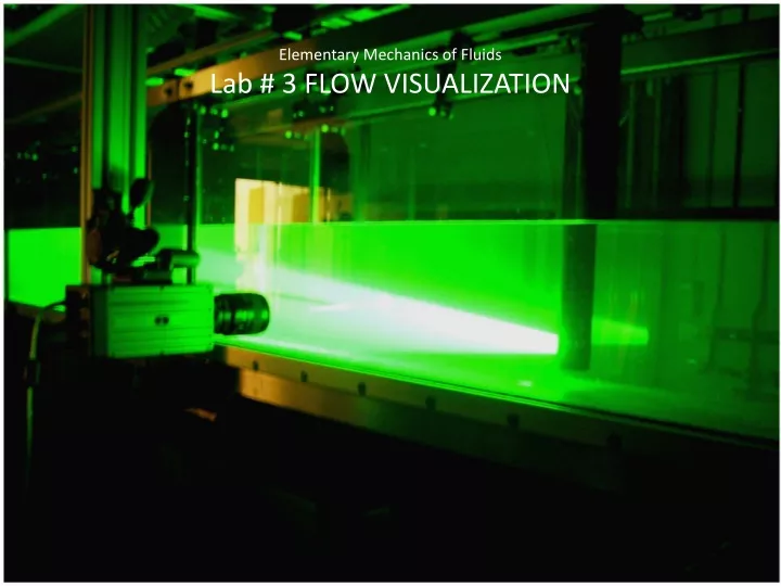
Nd:YAG Laser System Components Flume Laser Beam Nano sense Camera Control Unit Traverse System Timing Hub Chiller Flow visualization Lab
PIV Measurements • PIV is a non-intrusive, whole field optical technology used for obtaining velocity information by suspending ‘seeding’ particles in a fluid in motion. • Measurement is based on particle displacement over a known time interval. • The system uses a light source (Laser) and a nano-sense camera which are synchronized. Flow visualization Lab
PIV Processing stages Flow visualization Lab
Light source, sheet formation and Seeding particles Double Cavity Nd:YAG Laser: • Pulses of short duration (5-10 ns) • Vast range of Output energy and repetition rates providing powerful light flash. • Optic components added for transformation of IR to Visible light and recombination along same optical path Seeding Particles: • Hollow glass spheres • Diameter comparable to light source wavelength (in accordance with Lorenz Mie theory) • Light scattering sideways is of interest Flow visualization Lab
Flow around a Glass Cylinder Flow visualization Lab
Clip depicting particle movement Flow visualization Lab
Correlations • Image is subdivided into Interrogation areas (IA), each IA has a correlation function • Different types such as Adaptive, Cross and Average correlations • Calculation of velocity vectors with initial IA, applying refinement steps and using intermediary results as input for the next IA • Application of Validation Methods and IA offset scheme • Averaging the correlation to increase the signal-to-noise-ratio significantly and generating clear correlation peaks • Cross-correlations for single frame images Flow visualization Lab
Filters • Average filter used to output vector maps by arithmetic averaging, individual vectors smoothed out • Substitution of vectors with uniformly weighted average over a user defined area • To enhance the results of measurement, a coherence filter applied to the raw velocity field to modify the inconsistent vectors • Application of filters improves the acquired parent data, various vector and scalar maps can be derived Flow visualization Lab
Vector Statistics Output Flow visualization Lab
Scalar Map Sqrt (U2 + V2) Note: results are processed and shown downstream of the cylinder Flow visualization Lab
Scalar Map for Vorticity Vorticity measures the “swirl” or the “local spin” of the flow Note: results are processed and shown downstream of the cylinder Flow visualization Lab
Typical recommendations for PIV measurements around a cylinder: • At least 5 seeding particles per IA to minimize “loss of pairs” • Use cross-correlation than auto correlation methods • Use of Guassian window function to eliminate noise due to cyclic convolution • Use of filters to optimize the effectiveness of sub-pixel interpolation • Maximum permissible displacement of particles be 25% of the IA • Minimize effects of zero velocity biasing Flow visualization Lab
Conclusion • Time resolved PIV is an effective tool for fluid flow visualization, determination of velocity and related fluid properties • Non-intrusive method, high speed data processing, high degree of accuracy • Can be used fairly easily to depict the flow characteristics around objects such as cylinders and airfoils • Scope for more precision as regards to use of camera and multiple cavity laser technology • Valuable for academic and research purposes Flow visualization Lab