Download
1 / 12
120 likes | 305 Views
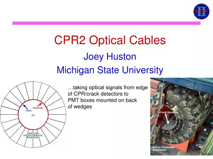
CPR2 Optical Cables. …taking optical signals from edge of CPR/crack detectors to PMT boxes mounted on back of wedges. Joey Huston Michigan State University. Optical cables. Optical cables ~3-5m long take optical signals to PMT boxes mounted on back of wedges

E N D
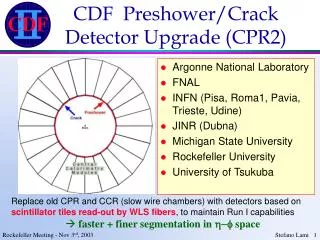
CPR2 Optical Cables …taking optical signals from edge of CPR/crack detectors to PMT boxes mounted on back of wedges Joey Huston Michigan State University
Optical cables • Optical cables ~3-5m long take optical signals to PMT boxes mounted on back of wedges • diameter of clear fiber steps up to 1.1 mm in order to reduce alignment issues
Routing • Clear fibers are routed into 4 connectors of 16 channels each • connector D has 6 fibers from CPR and 10 from crack detector
Light-tighting • Black plastic covering for optical cable • Sliding plastic shroud for connector region
Clear fiber attentuation length • Clear fiber tests conducted at Rockefeller • Attenuation length best fitted to 2-components • PolyHiTech and Kuraray give similar results • PolyHiTech used for cables • 1000 m of Kuraray purchased for spares
Optical cable installation issues • Main Installation Issue for Preshower/Crack. • Length of cables is at best an educated guess. Need full scaffold and PMT boxes installed to measure best lengths. • extra 50 cm of cable causes 10% loss of light yield, and is a good place to cause fiber damage. • PMT box placement changes depending on wedge, and complete plan changed 4 times in last long access. • Plan is to make 50% of the optical cables before shutdown with educated guess, then after first week of shutdown make the rest (takes about 1.5 weeks per arch).
Determining cable lengths Determine step-by-step the additional lengths to add to these straight-line paths for optical cables. Approximate distances to add to the clear fiber lengths (for normal wedges) 110 mm -- middle of wedge to farthest CPR connector 205 mm=8” -- distance across side window on wedge 915 mm=36” -- horizontal distance across wedge to PMT box 305 mm=12” -- vertical distance to PMT box 305 mm=12” -- lateral distance to PMT box 150 mm -- safety margin (?)
Step 2: The window height is known to be 8”, and the cables must enter the back of the wedge from the farther point on the window. Assume a straight line from the middle point on bottom of window to middle point on top of window. 8” = 205 mm
Signal and HV cables Electronics crate Optical cables PMT access Black LED fibers for EM Cal Step 3: 3’ from entry point at window to middle of plate holding PMT boxes. 3’ = 915 mm 3’ to middle
Step 4: Plate that box sits on could be as high as 6”. Top cable for the box is about 6” high. So add about 12”=305mm for a vertical rise from the base of wedge to the PMT box. Step 5: Optical cable entry point in the window will likely not line up with PMT box hole. Assume a 12”=305mm travel across wedge for this.
Tight spots Tight fit in last long access! Scraped sides of connector on 1 arch, fine on the other arch. MSU has since trimmed connector by 1.5 mm.
4 PMT boxes mounted on sides of monkey bars 6 PMT boxes mounted on “normal” wedges 2 PMT boxes mounted on inside of cradle