Download
1 / 55
570 likes | 969 Views
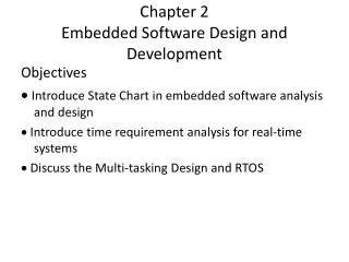
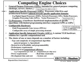
Chapter 3 General-Purpose Processors: Software. Outline. Introduction Basic Architecture Operation Programmer’s View Development Environment Application-Specific Introduction-Set Processors (ASIPs) Selecting a Microprocessor General-Purpose Processor Design Summary. Introduction.

E N D
Outline • Introduction • Basic Architecture • Operation • Programmer’s View • Development Environment • Application-Specific Introduction-Set Processors (ASIPs) • Selecting a Microprocessor • General-Purpose Processor Design • Summary
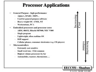
Introduction • General-Purpose Processor • Processor designed for a variety of computation tasks • Benefits for using a general-purpose processor to implement embedded systems: • Low unit cost, in part because manufacturer spreads NRE over large numbers of units • Motorola sold half a billion 68HC05 microcontrollers in 1996 alone • Carefully designed for critical components since higher NRE is acceptable • Can yield good performance, size and power • Low NRE cost, short time-to-market/prototype, high flexibility • User just writes software; no processor design
Processor Control unit Datapath ALU Controller Control /Status Registers PC IR I/O Memory Basic Architecture • A general-purpose processor consists of • a datapaath • a control unit • tightly linked with a memory
Processor Control unit Datapath ALU Controller Control /Status Registers PC IR I/O Memory Basic Architecture (Cont.) • Control unit and datapath • Note similarity to single-purpose processor • Key differences • Datapath is general • Control unit doesn’t store the algorithm – the algorithm is “programmed” into the memory
+1 Datapath Operations • Datapath consists of circuit for transforming data and for storing temporary data. • Load • Read memory location into register Processor Control unit Datapath ALU Controller Control /Status Registers 10 11 • ALU operation • Input certain registers through ALU, store back in register PC IR I/O ... Memory 10 • Store • Write register to memory location 11 ...
Processor Control unit Datapath ALU Controller Control /Status Registers PC IR R0 R1 I/O ... Memory 100 load R0, M[500] 500 10 101 inc R1, R0 501 ... 102 store M[501], R1 Control Unit • Control unit: configures the datapath operations • Sequence of desired operations (“instructions”) stored in memory – “program” • Consists of circuit for retrieving program instructions and for moving data to, from, and through the datapath according to those instruction • Consists: • a program counter (PC) holding the next instruction address • a instruction register (IR) holding the fetched instruction • a controller consisting of a state register plus next-state and control logic
Processor Processor Program memory Data memory Memory (program and data) Harvard Princeton Memory • Two memory architectures • Princeton • Simpler hardware connection to memory • Harvard • Simultaneous program and data memory access • Improved performance
Fast/expensive technology, usually on the same chip Processor Cache Memory Slower/cheaper technology, usually on a different chip Memory (Cont.) • RAM • ROM • For program, constant data • On-chip or off-chip • Memory access may be slow • Cache is small but fast memory close to processor • Holds copy of part of memory • Cache hits and misses
Processor Control unit Datapath ALU Controller Control /Status Registers PC IR R0 R1 I/O ... Memory 100 load R0, M[500] 500 10 101 inc R1, R0 501 ... 102 store M[501], R1 Control Unit Operation • Instruction cycle – broken into several sub-operations, each one clock cycle, e.g.: • Fetch: Get next instruction into IR • Decode: Determine what the instruction means • Fetch operands: Move data from memory to datapath register • Execute: Move data through the ALU • Store results: Write data from register to memory • A single instruction may take several cycles to complete
Control Unit Sub-Operations • Fetch • Get next instruction into IR • PC: program counter, always points to next instruction • IR: holds the fetched instruction Processor Control unit Datapath ALU Controller Control /Status Registers PC IR 100 R0 R1 load R0, M[500] I/O ... Memory 100 load R0, M[500] 500 10 101 inc R1, R0 501 ... 102 store M[501], R1
Control Unit Sub-Operations • Decode • Determine what the instruction means Processor Control unit Datapath ALU Controller Control /Status Registers PC IR 100 R0 R1 load R0, M[500] I/O ... Memory 100 load R0, M[500] 500 10 101 inc R1, R0 501 ... 102 store M[501], R1
Control Unit Sub-Operations • Fetch operands • Move data from memory to datapath register Processor Control unit Datapath ALU Controller Control /Status Registers 10 PC IR 100 R0 R1 load R0, M[500] I/O ... Memory 100 load R0, M[500] 500 10 101 inc R1, R0 501 ... 102 store M[501], R1
Control Unit Sub-Operations • Execute • Move data through the ALU • This particular instruction does nothing during this sub-operation Processor Control unit Datapath ALU Controller Control /Status Registers 10 PC IR 100 R0 R1 load R0, M[500] I/O ... Memory 100 load R0, M[500] 500 10 101 inc R1, R0 501 ... 102 store M[501], R1
Control Unit Sub-Operations • Store results • Write data from register to memory • This particular instruction does nothing during this sub-operation Processor Control unit Datapath ALU Controller Control /Status Registers 10 PC IR 100 R0 R1 load R0, M[500] I/O ... Memory 100 load R0, M[500] 500 10 101 inc R1, R0 501 ... 102 store M[501], R1
Processor Fetch ops Store results Control unit Datapath Fetch Decode Exec. ALU Controller Control /Status Registers 10 PC IR R0 R1 load R0, M[500] I/O ... Memory 100 load R0, M[500] 500 10 101 inc R1, R0 501 ... 102 store M[501], R1 Instruction Cycles PC=100 clk 100
Processor Control unit Datapath ALU Controller +1 Control /Status Registers Fetch ops Store results Fetch Decode Exec. 11 PC IR R0 R1 inc R1, R0 I/O ... Memory 100 load R0, M[500] 500 10 101 inc R1, R0 501 ... 102 store M[501], R1 Instruction Cycles PC=100 Fetch ops Store results Fetch Decode Exec. clk PC=101 clk 10 101
Processor Control unit Datapath ALU Controller Control /Status Registers PC IR R0 R1 store M[501], R1 Fetch ops Store results Fetch Decode Exec. I/O ... Memory 100 load R0, M[500] 500 10 101 inc R1, R0 501 11 ... 102 store M[501], R1 Instruction Cycles PC=100 Fetch ops Store results Fetch Decode Exec. clk PC=101 Fetch ops Store results Fetch Decode Exec. clk 10 11 102 PC=102 clk
Processor Control unit Datapath ALU Controller Control /Status Registers PC IR I/O Memory Architectural Considerations • N-bit processor • N-bit ALU, registers, buses, memory data interface • Embedded: 8-bit, 16-bit, 32-bit common • Desktop/servers: 32-bit, even 64 • PC size determines address space
Processor Control unit Datapath ALU Controller Control /Status Registers PC IR I/O Memory Architectural Considerations • Clock frequency • Inverse of clock period • Must be longer than longest register to register delay in entire processor • Memory access is often the longest
Speed up a processor • Performance can be improved by: • Faster clock (but there’s a limit) • Pipelining: slice up instruction into stages, overlap stages • Multiple ALUs to support more than one instruction stream
Pipelining Wash 1 2 3 4 5 6 7 8 1 2 3 4 5 6 7 8 Non-pipelined Pipelined Dry 1 2 3 4 5 6 7 8 1 2 3 4 5 6 7 8 Time Time non-pipelined dish cleaning pipelined dish cleaning
Fetch-instr. 1 2 3 4 5 6 7 8 Decode 1 2 3 4 5 6 7 8 Fetch ops. 1 2 3 4 5 6 7 8 Pipelined Execute 1 2 3 4 5 6 7 8 Instruction 1 Store res. 1 2 3 4 5 6 7 8 Time pipelined instruction execution Pipelining: Increasing Instruction Throughput • Increasing Instruction Throughput • Pipelined instruction execution
Pipelining (Cont.) • For pipelining to work well • instruction execution must be decomposable into roughly equal length states • instructions should each require the same number of cycles • Branches pose a problem for pipelining • since we don’t know the next instruction until the current instruction has reached the execute state. • Solution: • Stall the pipeline , waiting for the execute state before fetching the next instruction • Brach prediction
Superscalar and VLIW Architectures • Use multiple ALUs to support more than one instruction stream • Superscalar • A superscalar microprocessor can execute two or more scalar operations in parallel, requiring two or more ALUs. • Scalar: non-vector operations • Fetches instructions in batches, executes as many as possible • May require extensive hardware to detect independent instructions • VLIW (very long instruction word) • A type of static superscalar architecture that encodes several operations in a single machine instruction • each word in memory has multiple independent instructions • Relies on the compiler to detect and schedule instructions • Currently growing in popularity
Programmer’s View • Programmer doesn’t need detailed understanding of architecture • Instead, needs to know what instructions can be executed • Two levels of instructions: • Assembly level • Structured languages (C, C++, Java, etc.) • Most development today done using structured languages • But, some assembly level programming may still be necessary • Drivers: portion of program that communicates with and/or controls (drives) another device • Often have detailed timing considerations, extensive bit manipulation • Assembly level may be best for these
Instruction 1 opcode operand1 operand2 Instruction 2 opcode operand1 operand2 Instruction 3 opcode operand1 operand2 Instruction 4 opcode operand1 operand2 ... Instruction Set • Instruction Set • Describes the bit configurations allowed in the IR • Defines the legal set of instructions for that processor • Instructions stored in memory.
Assembly-Level Instructions • Instruction categories: • Data transfer • memory/register, register/register, register/ I/O, etc. • Arithmetic/logical • configure ALU to carry out particular function, move register through ALU and back • Branches • determine next PC value when not just PC+1 • Unconditional jumps, conditional jumps, or procedure call and return
Addressing Modes • The operand field may indicate the data’s location through one of several addressing modes. • Addressing modes: • Immediate addressing • The operand field contains the data itself • Register addressing • The operand field contains the address of a datapath register in which the data resides • Register-indirect addressing • The operand field contains the address of a register, which in turn contains the address of a memory locaiton for data • Direct addressing • The operand field contains the memory address for data • Indirect addressing • The operand field contains the address of a memory location, which in turn contains the address of a memory location for data
Addressing Modes Addressing mode Register-file contents Memory contents Operand field Immediate Data Register-direct Register address Data Register indirect Register address Memory address Data Direct Memory address Data Indirect Memory address Memory address Data
A Simple (Trivial) Instruction Set Assembly instruct. First byte Second byte Operation MOV Rn, direct 0000 Rn direct Rn = M(direct) MOV direct, Rn 0001 Rn direct M(direct) = Rn Rm MOV @Rn, Rm 0010 Rn M(Rn) = Rm MOV Rn, #immed. 0011 Rn immediate Rn = immediate ADD Rn, Rm 0100 Rn Rm Rn = Rn + Rm SUB Rn, Rm 0101 Rn Rm Rn = Rn - Rm JZ Rn, relative 0110 Rn relative PC = PC+ relative (only if Rn is 0) opcode operands
C program Equivalent assembly program 0 MOV R0, #0; // total = 0 1 MOV R1, #10; // i = 10 2 MOV R2, #1; // constant 1 int total = 0; for (int i=10; i!=0; i--) total += i; // next instructions... 3 MOV R3, #0; // constant 0 Loop: JZ R1, Next; // Done if i=0 5 ADD R0, R1; // total += i 6 SUB R1, R2; // i-- 7 JZ R3, Loop; // Jump always Next: // next instructions... Sample Programs • Try some others • Handshake: Wait until the value of M[254] is not 0, set M[255] to 1, wait until M[254] is 0, set M[255] to 0 (assume those locations are ports). • (Harder) Count the occurrences of zero in an array stored in memory locations 100 through 199.
Programmer Considerations • Program and data memory space • Embedded processors often very limited • e.g., 64 Kbytes program, 256 bytes of RAM (expandable) • Registers: How many are there? • Only a direct concern for assembly-level programmers • General-purpose, special-function registers • I/O • How communicate with external signals? • Interrupts • The type of interrupts supported by the processor • Must write ISR (interrupt service routine) when necessary
LPT Connector Pin I/O Direction Register Address 1 Output 0th bit of register #2 2-9 Output 0th bit of register #0 10,11,12,13,15 Input 6,7,5,4,3th bit of register #1 14,16,17 Output 1,2,3th bit of register #2 Example: parallel port driver • Using assembly language programming we can configure a PC parallel port to perform digital I/O • write and read to three special registers (in an 8255A Peripheral Interface Controller chip) to accomplish parallel communication on the PC • this table provides list of parallel port connector pins and corresponding register location • Example : parallel port monitors the input switch and turns the LED on/off accordingly PC parallel port signals and associated registers
LPT Connector Pin I/O Direction Register Address 1 Output 0th bit of register #2 2-9 Output 0th bit of register #0 10,11,12,13,15 Input 6,7,5,4,3th bit of register #1 14,16,17 Output 1,2,3th bit of register #2 PC Parallel Port Example ; This program consists of a sub-routine that reads ; the state of the input pin, determining the on/off state ; of our switch and asserts the output pin, turning the LED ; on/off accordingly .386 CheckPort proc push ax ; save the content push dx ; save the content mov dx, 3BCh + 1 ; base + 1 for register #1 in al, dx ; read register #1 and al, 10h ; mask out all but bit # 4 cmp al, 0 ; is it 0? jne SwitchOn ; if not, we need to turn the LED on SwitchOff: mov dx, 3BCh + 0 ; base + 0 for register #0 in al, dx ; read the current state of the port and al, f7h ; clear first bit (masking) out dx, al ; write it out to the port jmp Done ; we are done SwitchOn: mov dx, 3BCh + 0 ; base + 0 for register #0 in al, dx ; read the current state of the port or al, 01h ; set first bit (masking) out dx, al ; write it out to the port Done: pop dx ; restore the content pop ax ; restore the content CheckPort endp extern “C” CheckPort(void); // defined in // assembly void main(void) { while( 1 ) { CheckPort(); } } x86 assembly language program
Operating System • Optional software layer providing low-level services to a program (application). • File management, disk access • Keyboard/display interfacing • Scheduling multiple programs for execution • Or even just multiple threads from one program • Program makes system calls to the OS • OS abstracts away the details of the underlying hardware and provides the application layer an interface to the hardware through the system call mechanism. system call invocation DB file_name “out.txt” -- store file name MOV R0, 1324 -- system call “open” id MOV R1, file_name -- address of file-name INT 34 -- cause a system call JZ R0, L1 -- if zero -> error . . . read the file JMP L2 -- bypass error cond. L1: . . . handle the error L2:
Development Environment • Development processor • The processor on which we write and debug our programs • Usually a PC • Target processor • The processor that the program will run on in our embedded system • Often different from the development processor Development processor Target processor
Library Software Development Process • Compilers • Cross compiler • Runs on one processor, but generates code for another • Assemblers • Linkers • Debuggers • Profilers • Typically, combined into a single integrated development environment (IDE) Asm. File C File C File Compiler Assembler Binary File Binary File Binary File Linker Debugger Exec. File Profiler Verification Phase Implementation Phase
(a) (b) Implementation Phase Implementation Phase Verification Phase Development processor Debugger/ ISS External tools Programmer Verification Phase Emulator Software design process • desktop • embedded
Running a Program • If development processor is different than target, how can we run our compiled code? Two options: • Download to target processor • Simulate • Simulation • One method: Hardware description language • But slow, not always available • Another method: Instruction Set Simulator (ISS) • Runs on development processor, but executes instructions of target processor
Instruction Set Simulator For A Simple Processor #include <stdio.h> typedef struct { unsigned char first_byte, second_byte; } instruction; instruction program[1024]; //instruction memory unsigned char memory[256]; //data memory void run_program(int num_bytes) { int pc = -1; unsigned char reg[16], fb, sb; while( ++pc < (num_bytes / 2) ) { fb = program[pc].first_byte; sb = program[pc].second_byte; switch( fb >> 4 ) { case 0: reg[fb & 0x0f] = memory[sb]; break; case 1: memory[sb] = reg[fb & 0x0f]; break; case 2: memory[reg[fb & 0x0f]] = reg[sb >> 4]; break; case 3: reg[fb & 0x0f] = sb; break; case 4: reg[fb & 0x0f] += reg[sb >> 4]; break; case 5: reg[fb & 0x0f] -= reg[sb >> 4]; break; case 6: pc += sb; break; default: return –1; } } return 0; } int main(int argc, char *argv[]) { FILE* ifs; If( argc != 2 || (ifs = fopen(argv[1], “rb”) == NULL ) { return –1; } if (run_program(fread(program, sizeof(program),ifs)) == 0) { print_memory_contents(); return(0); } else return(-1); }
(a) (b) Implementation Phase Implementation Phase Verification Phase Development processor Debugger/ ISS External tools Programmer Verification Phase Emulator Testing and Debugging • Instruction Set simulator (ISS) or virtual machine (VM) • Debuggers run on development processor but execute code designed for target processor • Mimic or simulate the function of target processor • doesn’t interact with real environment
(a) (b) Implementation Phase Implementation Phase Verification Phase Development processor Debugger/ ISS External tools Programmer Verification Phase Emulator Testing and Debugging (Cont.) • Emulator • Support debugging of the program while it executes on the target processor • Typically consists of a debugger coupled with a board connected to the desktop processor via a cable • The board consists of target processor plus some support circuitry. • Such an in-circuit emulator enables one to control and monitor the program’s execution in the actual embedded system circuit
(a) (b) Implementation Phase Implementation Phase Verification Phase Development processor Debugger/ ISS External tools Programmer Verification Phase Emulator Testing and Debugging (Cont.) • Device programmers • Download a binary machine program from the development processor’s memory into target processor’s memory
(a) (b) Implementation Phase Implementation Phase Verification Phase Development processor Debugger/ ISS External tools Programmer Verification Phase Emulator Testing and Debugging (Cont.) • ISS • Gives us control over time – set breakpoints, look at register values, set values, step-by-step execution, ... • But, doesn’t interact with real environment • Download to board • Use device programmer • Runs in real environment, but not controllable • Compromise: emulator • Runs in real environment, at speed or near • Supports some controllability from the PC
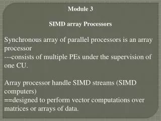
Application-Specific Instruction-Set Processors (ASIPs) • General-purpose processors • Sometimes too general to be effective in demanding application • e.g., video processing – requires huge video buffers and operations on large arrays of data, inefficient on a GPP • But single-purpose processor has high NRE, not programmable • ASIPs – targeted to a particular domain • Contain architectural features specific to that domain • e.g., embedded control, digital signal processing, video processing, network processing, telecommunications, etc. • Still programmable
A Common ASIP: Microcontroller • For embedded control applications • Reading sensors, setting actuators • Mostly dealing with events (bits): data is present, but not in huge amounts • e.g., VCR, disk drive, digital camera (assuming SPP for image compression), washing machine, microwave oven • Microcontroller features • On-chip peripherals • Timers, analog-digital converters, serial communication, etc. • Tightly integrated for programmer, typically part of register space • On-chip program and data memory • Direct programmer access to many of the chip’s pins • Specialized instructions for bit-manipulation and other low-level operations
Another Common ASIP: Digital Signal Processors (DSP) • DSPs are processors highly optimized for processing large amounts of data • For signal processing applications • Large amounts of digitized data, often streaming • Data transformations must be applied fast • e.g., cell-phone voice filter, digital TV, music synthesizer • DSP features • Several instruction execution units • Multiple-accumulate single-cycle instruction, other instrs. • Efficient vector operations – e.g., add two arrays • Vector ALUs, loop buffers, etc.
Trend: Even More Customized ASIPs • In the past, microprocessors were acquired as chips • Today, we increasingly acquire a processor as Intellectual Property (IP) • e.g., synthesizable VHDL model • Opportunity to add a custom datapath hardware and a few custom instructions, or delete a few instructions • Can have significant performance, power and size impacts • Problem: need compiler/debugger for customized ASIP • Remember, most development uses structured languages • One solution: automatic compiler/debugger generation • e.g., www.tensillica.com • Another solution: retargettable compilers • e.g., www.improvsys.com (customized VLIW architectures)
Selecting a Microprocessor • Issues • Technical: speed, power, size, cost • Other: development environment, prior expertise, licensing, etc. • Speed: how to evaluate a processor’s speed? • Clock speed – but instructions per cycle may differ • Instructions per second – but work per instruction may differ • Dhrystone: Synthetic benchmark, developed in 1984. Dhrystones/sec. • MIPS: 1 MIPS = 1757 Dhrystones per second (based on Digital’s VAX 11/780). A.k.a. Dhrystone MIPS. Commonly used today. • So, 750 MIPS = 750*1757 = 1,317,750 Dhrystones per second • SPEC: set of more realistic benchmarks, but oriented to desktops • EEMBC – EDN Embedded Benchmark Consortium, www.eembc.org • Suites of benchmarks: automotive, consumer electronics, networking, office automation, telecommunications