Download
1 / 20
210 likes | 518 Views
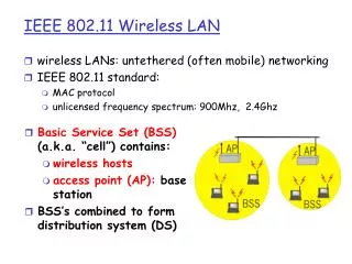
2.4-GHZ RF TRANSCEIVER FOR IEEE 802.11B WIRELESS LAN. UF# 1593 6620. Objective:. Design of a system level 2.4 GHz RF-transceiver for wireless LAN Software used: Ansoft Syscal MatLab. IEEE 802.11b Specifications. Receiver:

E N D
2.4-GHZ RF TRANSCEIVERFOR IEEE 802.11B WIRELESS LAN UF# 1593 6620
Objective: • Design of a system level 2.4 GHz RF-transceiver for wireless LAN • Software used: • Ansoft • Syscal • MatLab
IEEE 802.11b Specifications • Receiver: • Frequency range: 2.4 – 2.4835 GHz • Bit Rate: 1/2/5.5/11 Mb/s • BW: 22 MHz • Sensitivity: -80/-76 dBm • FER: 8% • Adjacent channel Rej: 41 dB • Max Power level: -15 dBm • Receiver NF: 8.3 dB
Transmitter: • Max transmit power: 30 dBm • Transmit Spectrum mask fc = 0 dBr fc -22MHz <f < fc -11MHz -30 dBr fc -11MHz < f < fc +22MHz -30 dBr f < fc-22MHz -50 dBr f > fc+22MHz -50 dBr • Center frequency tolerance:+/- 25 MHz
Transmitter Specifications: a) o/p power spectrum : -15 dBm b) 11 Mb/s CCK modulation c) 1 Mb/s Data rate d) Barker Code: 10110111000
IF Mixer: AD8343 < Analog Devices > Conversion Gain: 7.1 dB Input IP3: 16.5 dBm LO power: 20 dbm Noise Figure: 14.1 dB Input P1 dB: 2.8 dB IF-SAW filter < BethelTronix>: Center Frequency: 300 MHz. Stopband Rejection: 53 dB. Insertion Loss: 4.5 dB Specification of parts used in TX
RF Mixer: HMC400MS8 < Hittite Corporation > Conversion Loss: 8.8 dB Input IP3: 35 dBm LO power: 18 dBm Noise Figure: 8.8 Input P1 dB: 22 dBm RF- Band Pass Filter: Insertion Loss: 1.1 dB Center Frequency: 2400 MHz. Attenuation at cutoff frequencies: 50dB Power amplifiers: HMC287MS8 < Hittite Corporation > Gain: 21 dB Noise Figure: 2.2 dB OP3: 7 dBm OP1: 3 dBm GBH120_214 < Alpha > Gain: 18 dB IP3: 33 dBm Noise Figure: 4.5 dB
RF- Band Pass Filter < Butterworth >: Insertion Loss: 1.1 dB Center Frequency: 2400 MHz. Attenuation at cutoff frequencies: 50 dB Mixer HMC400MS8 < Hittite Corporation > Conversion Loss: 8.8 dB Input IP3: 35 dBm LO power: 18 dBm Noise Figure: 8.8 Input P1 dB: 22 dBm LNA HMC287MS8 < Hittite Corporation > Gain: 21 dB Noise Figure: 2.2 dB OP3: 7 dBm OP1: 3 dBm IF-SAW filter < BethelTronix>: Center Frequency: 300 MHz. Stopband Rejection: 53 dB. Insertion Loss: 4.5 dB Specifications of the parts used in RX
AD8343 < Analog Devices > Conversion Gain: 7.1 dB Input IP3: 16.5 dBm LO power: 20 dbm Noise Figure: 14.1 dB Input P1 dB: 2.8 dB Low Pass Filter < LPM50001, Micro-tronics > Insertion Loss: 3 dB Pass band: 0-18 MHz Rejection: 50 dB Stop band: 19.1 to 100 MHz. VSWR: 1.5:1
Receiver Requirements • SNR FER = 810-2 1 Frame = 1024 8 bits Let F be the probability that a frame is received correctly, F100 = 0.92 Let (1-P) be the probability a bit is in error P1024*8 = F P = 0.92(1/ (1024*8*100)) 1-P = 1.0110-7 Therefore, BER = 1.0110-7 E/N = (erfinv (1-2*BER)) ^2 E/N = 13.5 dB S/N = 13.5-3 S/N = 10.5 dB Adhering to a stricter margin, the S/N can be decided to be 12.3 dB
Noise Figure Sensitivity = NF + SNR + Noise Floor. -80 = -174 + 10×log (22×106) +12+NF NF = 8.3 dB The noise figure of the receiver should be <= 8.3 dB. • IIP3 Adjacent channel carrier power= sensitivity+41 dB Carrier power of channel of interest = sensitivity+6 dB Therefore the MDS (minimum discernable signal) is –80+6-SNR= -80+6-10.5 = -84.5 Carrier power of adjacent channel = -80+41= -39 IIP3 = -39 + (-39-(-84.5))/2 = -16.25 Therefore IIP3 for a receiver should be higher than –16.25.
IIP3 From the previous figure, we find the IIP3 of the receiver to be -16.13 dBm, which is >-16.35 dBm • Noise Figure The NF of the receiver system is 8.46 dB
Summary-Transceiver Specifications • Heterodyne Architecture: IF=300 MHz , RF=2.4 GHz • Transmitter Specifications Data Rate = 1 Mb/s interleaved on 11 Mb/s Barker Code O/P Power = -15 dBm • Receiver Specifications Noise Figure = 8.46 dB Gain = 20.20 OIP3 = 4.07 dBm Min SNR = 12.3