Download
1 / 42
420 likes | 594 Views
R&D status of ILC Positron Source KURIKI Masao (Hiroshima/KEK) 구리기 마사오 ( 히로시마 대학 ). Table of Contents. Introduction RDR baseline configuration and its R&D. Alternative configuration and its R&D. TDP for ILC positron source Summary. ILC and Positron Source.

E N D
R&D status of ILC Positron Source KURIKIMasao(Hiroshima/KEK) 구리기마사오 (히로시마대학)
Table of Contents • Introduction • RDR baseline configuration and its R&D. • Alternative configuration and its R&D. • TDP for ILC positron source • Summary
ILC and Positron Source • Undulator is the baseline design. • Two alternatives: • Conventional (electron driven) is a fall back. • Laser Compton is an advanced alternative. • Any schemes are not fully established. Need a certain amount of R&D for ILC positron source.
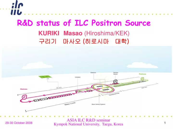
Baseline Design • It relies upon gamma rays generated by passing 150 GeV electron through 168m undulator. • Undulator is “inserted” to part way of ML (150GeV). • A positron source driven by 0.5 GeV electron is a back up for high availability and machine commissioning.
R&D efforts for the baseline (1) • This system is a totally new approach; Feasibility of the system should be confirmed in various levels. • Devices • System and sub-system • In addition, the ILC baseline e+ source is not an isolated system from the whole ILC and has inter-system dependencies. • Careful considerations are necessary from the system point of view. • E+ is generated at the same time for the collision. • E+ time structure is identical to that in ML.
R&D efforts for the baseline (2) • The R&D efforts for critical devices are on going. • Super-conducting helical undulator. • Rotating conversion target. • Capture devices (pending due to no budget). • Several considerations from the system engineering point of view have been made. • E+ timing issue : a mathematical puzzle among DR harmonic number, bunch spacing in ML, round trip duration from e- DR to e+ DR, etc. • Keep Alive e+ source : machine commissioning, fast recovery from the system failure,etc.
Undulator Cryo-module Overview 50K Al Alloy Thermal shield. Supported from He bath U beam Support rod Stainless steel vacuum vessel with Central turret Stainless Steel He bath contains100L liq He. Supported by 4 rods attached to the vacuum vessel U Beam used to support/align the magnet. Beam Tube Magnet cooled to 4.2K by liq He in bath. S Carr
Undulator Cryomodule U Beam Heat Shield Helical Undulator He Vessel
Quench Test & Field Measurement • All two magnets finally satisfied the specification. • Field profile is measured by hall probe, showing a good quality.
Conversion Target • Water-cooled electromagnet • Variable pole gap (0mm to 160mm) • Peak field > 1 T at wheel • Ti alloy wheel. Photon beam Ken Davies - Daresbury Laboratory • Torque Sensor • 15 kW drive motor L Jenner
Target Prototype Experiment will start when personnel guards are in place Should be completed by end of 2008
Matching Device • The generated positrons is a point like with a large transverse momentum spread. • That should be converted to a parallel beam for further acceleration; The matching device does it. • Depending on the matching device, it increases capture efficiency from 10% to 40%.
DC Solenoid • High field (6T) and high capture efficiency(30%). • Similar to other DC SC magnets; It is technically matured. • It is not feasible for ILC since 100's of kW of eddy current in a fast rotating metal target.
Shielded Flux Concentrator • Ramping from 0T to 7 T in 2cm (no field on target). • Capture Efficiency ~21% • Difficult technically to sustain 1ms pulse train length. • Further study needed to prove feasibility (prototype).
Quarter Wave Transformer • Ramping from 0T to 1 T in 5cm (no field on target). • Capture efficiency ~ 15%. • Technically matured and realizable (actual baseline).
Summary for baseline • R&D efforts for critical devices are in progress (undulator, target, etc). • Although Matching device is one of the most important, the R&D is stopped. • QWT is the only realistic solution at this moment and it should be actual baseline as long as there is no big progress on R&D for MD.
Alternative Design • e- driven scheme (conventional) and Laser Compton scheme are considered to be alternative schemes. • e- driven scheme is a back-up alternative. • Laser Compton is an advanced alternative. • Because the baseline design is a totally new approach, a conservative alternative is very important as a technical backup. • Laser Compton is attractive, but it is technically immature; It is advanced alternative.
e- driven scheme • e- drive beam impinges on a conversion target. • 6 GeV 2E+10 e- bunch. • Amorphous W (W-Re alloy), crystalline W, diamond, liquid Pb-Sn,etc. • Capture devices. • E+ booster up to 5 GeV: The technology depends on the pulse structure; SC for long pulse case (~1ms) and NC for short pulse case (<50μs). • The most important and difficult issue is conversion target.
CHANNELING FOR ILC & CLIC e+ sourceR. Chehab • A single target works for CLIC, but multi-target is needed for ILC limited by PEDD. • A single target might work for ILC in Low P parameter. “x” meters e+ Only the photons are impinging on the converter: that limits the energy deposition in the amorphous target. γ e- e+, e-, e- Crystal Amorphous Radiator Converter
Liquid lead target Driving motor • A prototype in BINP has been operated 20000h without any troubles. • Pb 90% Sn 10%, 300˚C, Cog-wheel pump. • Brazing technique for BN window has been established. Cog-wheel pump Vacuum pump Target head Liquid Pb-Sn jet in vacuum transport tubes
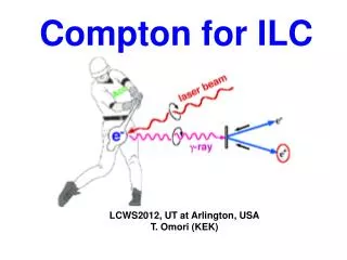
Laser Compton Scheme • A few GeV (1.8GeV for example) electron bunch collides with 1μm laser photon stored in optical cavity. • Several 10s MeV gamma impinges in a conversion target. • A dedicated electron driver is reasonable. • Obtaining enough positron, is a technical challenge. • High intensity electron beam: Linac, Storage ring, ERL • High intensity photon beam: High power laser, optical cavity. • Stacking scheme: DR stacking, Pre-DR, etc.
Compton Ring • A storage ring for electron driver:5.3nC, 6.2ns, 1ps, 1.8GeV, 0.6Jx5CP. • Positron bunch(Ne+:2.0E+8) is generated. • 10 bunches are stacked on a same bucket. This process is repeated 10 times with 10ms interval for beam cooling. • Finally, Ne+:2E+10 is obtained.
ERL • ERL(Energy Recovery Linac) is employed as the dedicated electron driver. • 0.48nC, 18.5ns (54MHz) ~ 26mA, E=1.8GeV • Nγ=2.3E+9 by 0.6 Jx5 CP, Ne+=2.0E+7 • By a semi-CW operation (50ms), 1000 times stacking in DR is performed and Ne+=2.0E+10 is obtained.
Pulsed Laser Injected Cavity R. Chiche
High power ps fiber amplifier E. Cormier
Experiment at KEK-ATF PD 16~28MeV 420mm γray CSI Electron beam Collision angle 12 degree e beam Mode lock laser γ/collison λ:1064nm 10W=28nJ , 2.8ns spacing Pulse length : 7ps Finess = 780 = 30 μm
Stacking Simulation F. Zimmermann • # of positron by a single collision is not sufficient -> need stacking. • Stacking simulation in DR (multi-turn injection) shows 10.6% of injected e+ are lost! stacking efficiency ~90%. • The tolerance of the injection loss would be qualified.
CLIC Compton Scheme • Collaboration on Positron Generationstrongly supported by CLIC and ILC managements (J.P. Delahaye@PosiPol08)
PosiPol-Collaboration • Laser-Compton has a large potential as a future technology. • Many common efforts can be shared in a context of various applications. • X-ray/SR sources for industrial and medical applications, • Beam diagnostics with Laser, • Polarized Positron Generation for ILC, CLIC, SuperB, .. • State-of-the-art technologies are quickly evolved with world-wide synergy. • PosiPol collaboration has been started in 2006. • The last annual meeting was held at Hiroshima in July 08. The next meeting will be held at near CERN in 2009.
WWW of PosiPol R&Ds 4th Generation light source ERL/Ring ILC e+ CLIC e+ e+ source Laser Compton SuperB Material Science Scientific Application LW monitor/ Polarimetry Medical applications X-ray source Optical Cavity Industrial applications e- source ILC, ERL High power laser
Technical Design Phase Minimum machine studies Re-baseline in 2010 (publish in interim report) • TDP is a multi-phase approach towards TDR. • TDP-1 is focused on • Risk mitigation • Cost reduction • TDP-2 is a real technical design phase based on the design established on TDP-1.
ILC Positron Source:MM • Undulator is moved to the end of ML (250GeV). • Energy scan <100GeV is difficult. • Dedicated pulse for e+ generation with ½L. • QWT instead of AMD, which has lower capture efficiency; The undulator length is 350m. • KAS share the common target with gamma1 source; yield is only 1% of the nominal intensity.
Further Considerations on MM • Improved Low P parameter : half # of bunches in a pulse. • It is a big fair wind for the electron driven. • Potential target damage, which is the most serious issue on electron driven scheme, is relaxed. • There are active R&D on noble ideas. • No doubts that Conventional is really “conventional”.
TDP Summary • Basic R&D is very important in TDP1. • Re-baseline at the end of TDP-1 is the mile-stone. • According to the investigation based on the latest technology, the status is: • The conventional method is important as a fall-back. Low P parameter and noble target technologies make it feasible and reliable. • Technical difficulty forces the undulator system bigger and bigger and it does not seem “mimimal machine”. • From the pure technical point of view, the baseline is the electron driven and undulator and laser compton are upgrade alternatives.
Summary • R&D status of ILC positron source is reviewed. • Undulator scheme is the baseline design. • SC helical Undulator, rotating rim target prototype. • Need study for matching device. • e- driven scheme is important as a backup. • There are several active R&Ds based on noble ideas. It is the best scheme for MM. • Laser Compton is an advanced alternative. • Aggressive R&D efforts. • Still need more technical maturity. • ILC-CLIC collaboration.
TDP-2 TDP-2: • Technical requirements documentation • Technical design work cost update • Value Engineering • Cost & Schedule • 18 month period
Liquid Pb-Sn Target • Liquid Pb target + BN window is very strong against high peak power, but less average power. • Pulsed operation (e.g. 100 bunches with 6.2ns spacing, 0.6μs, 150Hz) moderates thermal effects. • In the pulse operation, capture efficiency is higher and incident electron can be fewer. Average power (kW) Operation point Energy/100ps GeV/mm21012 • P. Logachov et al. in APAC2007
RDR Source Layout Ti-alloy fast rotating target for gamma -> e+ conversion. Capture devices : AMD or QWT + L-band NC accelerator with solenoid focusing. Backup source (500MeV e-, 10% intensity).


![[f´‚nE˘RIks]](https://cdn0.slideserve.com/636013/f-ne-riks-dt.jpg)