Download

1 / 16
160 likes | 328 Views
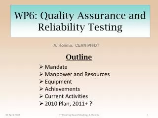
Quality Assurance, Testing and Burn-in WBS 1.1.4. Cecilia Gerber University of Illinois at Chicago. Production and Testing Sequence. WBS 1.1.1. WBS 1.1.2. WBS 1.1.2. Silicon Sensors. SVX4 Chips. Hybrids. Test Chips. Test Bare Hybrid (KU, CSUF). Probe Test Silicon Sensor in house

E N D
Quality Assurance, Testing and Burn-inWBS 1.1.4 Cecilia Gerber University of Illinois at Chicago
Production and Testing Sequence WBS 1.1.1 WBS 1.1.2 WBS 1.1.2 Silicon Sensors SVX4 Chips Hybrids Test Chips Test Bare Hybrid (KU, CSUF) Probe Test Silicon Sensor in house (KSU, SUNY-SB, Mexico) Mount components on Hybrid Test Hybrids (KU, CSUF) WBS 1.1.4 Outside Co. Burn-in Hybrids University Fermilab Build Detector Module
First L1 module Silicon Sensors Silicon Sensors Hybrid SVX4 Chips
Production and Testing Sequence II Build Detector Module WBS 1.1.4 Debug Detector Module Burn-in Detector Module Repair Detector Module/Staves QA of Detector Modules Build and Test Staves Assembly Detector WBS 1.1.5 Readout Detector WBS 1.1.2 & 1.1.7
Debug detector module Visual inspection Functionality test w/o HV Detector biasing (5V steps) Identify broken capacitors and pull bonds Maintain depletion voltage + 10V for 30 min Produce V-I & V-noise plots Done by physicist (tech to pull wire bonds) Assume 4 hours/module Burn-in Temperature sensor test at room temperature Long term test (60 hs) with detector biased and cooled Done by supervised non-expert physicists Results are used for detector grading Quality assurance Laser test, temperature cycles, pull test, etc Done by physicist on 10% of modules. Assume 1 week per module. Description of Tasks
Base Unit of Test Stand HW Used during RunIIA New for RunIIB SVX4, LV Power SVX4, LV Power Hybrid Hybrid DJC / / 50 - con.cable, 10 feet Module SASeq Module SASeq Purple Purple HV Card Card Bi - Ra Bi - Ra 2 ch. 2 ch. HV HV Hybrid T mon Hybr id VME VME DJC / / ADC ADC Module Module Prototype in hand for all new components
L1 module read out with new Run IIB “testing” HW Chip 2&3 are bonded to ELMA Sensor bias voltage 50 V, leakage current 1.5 mA
RunIIA Burn-in Setup: being adapted for RunIIB Modified Racks used as Dry&Cooled Testing Boxes Slider Plates allow easy setup of modules and provide cooling during Burn-in
Slider Plate for RunIIB • Slider Plate provides cooling for all type of modules during burn-in • Two modules are connected to one Purple Card via a Digital Jumper Cable per slider plate
Layout for module Burn-in One additional Rack houses all the readout electronics Modified Racks used as Dry&Cooled Testing Boxes Slide 3 of 4
Test Stations Count • Sidet lab AB bridge • 2 hybrid (32 ch) and 2 module (64 ch) burn-in stations • 1 QA laser station • 1 station used for diagnosis & repair • Lab D: 2 debugging stations • Lab C: 2 test stations for assembly • At remote institutions • KU,CSUF (hybrid testing and repair) • UIC, NW (code development) • KSU (electronic development) • Total of 4 burn-in and 11 testing stations • Run IIA: had 2 burn-in (16 channels each), 2 laser, 2 debug, 2 repair, 3 assembly, 1 development and 3 at remote institutions: 15 total. • Expect Run IIB modules to require less debugging and repair. Will perform QA on only a fraction of all modules. Assumed yield and number of spares will avoid lengthy repairs on individual modules.
Burn-in area in Sidet Bridge Two hybrid burn-in stations (16 hybrids each) Two module burn-in stations (32 modules each) Dry boxes for storage of modules and hybrids before and after burn-in testing One station devoted to diagnosis of defective modules One QA station connected to a laser on a movable table
Rates for Burn-in Testing • Two hybrid burn-in stations (16 channels each). • Two module burn-in stations (32 channels each). • Proposed rate of production is 40-60 modules/week • Average Run IIA production rate: 20 modules/week, peak Run IIA production rate: 25 modules/week. • Total Run IIA burn-in capacity: 32 • Corresponding capacity for Run IIB is 64 channels for module burn-in; 32 channels for hybrid burn-in. • Need to remember that hybrids and detectors may be burned-in more than once, and that module burn-in station can be used for hybrid burn-in (vice-versa not true).
Layer 0 & Layer 1 Modules get mounted directly on support structure – 6 per phi sector Test modules before/after installation on support structure Read out six modules together (check for cross talk/grounding problems) Layers 2 to 5 4 modules/stave Test individual modules before/after installation on stave Stave installed on bulkhead Read out four modules together (check for cross talk/grounding problems) Electrical Tests During Assembly Need 2 setups in LabC: • Stave assembly (4 channels) • Detector assembly (6 channels)
Summary • Testing and QA follows successful scheme used during Run2A • Testing capacity increased to keep up with expected production rate • Burn-in capacity of 32 hybrids + 64 modules • QA done on a fraction of all modules • Debugging rate of 4 hours per detector appropriate for Single Sided devices • Availability of spares will avoid extended repairs • Confident that testing plans are appropriate