Download
1 / 27
270 likes | 299 Views
Learn about LAN and WAN technologies in networking, including Ethernet, Token Ring, and Switched WANs, with a focus on key protocols and implementations.

E N D
Ch 3: Underlying Technologies Project 1 is posted on your course webpage Lecture
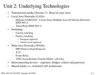
Internet – Underlying Technologies • As we mentioned before, the Internet is an interconnection of “backbone” networks JOINED together via routers, gateways and switches • Before getting into the higher level protocols, let’s cover more concerning the underlying technologies. Let’s talk about LANS and WANS and etc… • Internet is comprised of LANs, Point-to-Point WANs and Switched WANs • We will cover LANS: Ethernet, Token Ring (not in book), Wireless and FDDI Ring (not in book) • We will cover Pt-to-Pt WANs: Telephony Modem, DSL, Cable/Modem, T-Lines and SONET • We will cover Switched WANs: X.25, Frame Relay and ATM Token Ring (not in book) FDDI Ring (not in book) Lecture
In putting these technologies in perspective Most of the technologies we are about to highlight could be covered as a full blown course – in some cases, multiple courses We will look at each technology from a high level in gathering a general appreciation and understanding of the technology Lecture
LOCAL AREA NETWORKS (LANS) • LAN – a data communication system connecting multiple INDEPENDENT devices such computers, servers, printers, etc.. • Covers up to a certain geographical area – typically within a building or campus • Some Popular LANs: Token Ring, FDDI Ring, Ethernet, Wireless type LANs, and ATM LANs Lecture
Token Ring LAN • Token Ring is a protocol defined by IEEE 802.5 • Use a token passing ACCESS method • Token Passing Method • During idle times (network not being used), a token circulates • The token is passed station to station until a station needs to send data • When the station sends it’s data, it holds the token • The data (or frame) circulates and get re-generated by each station • The Rx takes in and COPY the frame (based on destination address) • The data then continues back to the original Tx • Token is then release to circulate Lecture
Token Ring layers • Uses the same layers as Ethernet (MAC and LLC) • LLC Layer – logical link control layer – performs the error and flow control routines (same as Ethernet) • MAC Layer – media access control layer –it implements the Token Passing Access Method (versus Ethernet’s CSMA/CD access method) Token Ring Lecture
Token Ring Data frame • Token Ring frame defines 3 types of frames: data, token and abort • Data Frame – carries a protocol data unit (actual data) and is addressed to a specific Rx (not broadcasted) • Token Frame – is the placeholder frame (token) and uses only 3 of the 9 fields (SD, AC and ED) • Abort Frame – doesn’t carry any info and is used to stop transmission • SD – start delimiter – alert and synch the Rx • AC – Access control - 3 bits set priority, 1 bit tells what type of frame, 1 bit is a monitor bit tells which station is monitoring or sending at the time, and 3 reservation bits for station wishing for access • FC – Frame control – 1 bit tells if PDU is control info or data, 7 bits is used by Token Ring (ie. tells how to use AC field info) • DA – Destination address • SA – Source Address • Data • CRC – cyclic redundancy check – error checking • ED – end delimiter – signals end of data • FS – frame status – intermediate stations can set it letting the Tx know they read it, Rx can set it letting the Tx know it was copied and can be discarded now Lecture
Token Ring Implementation • Token Ring is a series of shielded twisted pair transport medium linking each station into a ring • Because the token needs to pass through each station with in the ring, if a station is down, it could be a problem • Therefore, for each station, a switch is used to by pass the down (or disabled) station • These bypass switches are packaged together as a MAU – multi-station access unit NOTE: As we covered last lecture, don’t confuse the Ring Token technology with the Ring topology. With a ring topology approach, you would want to traverse in either direction (this is the main benefit of a ring topology) – explain Ethernet in ring topology. Lecture
FDDI Ring • FDDI stands for Fiber Distributed Data Interconnect • Data rate is the same as Fast Ethernet (100 Mbps) • Light signals versus electrical signals are used • Uses a token passing access method with self-healing • What do we mean by “self healing” ? Ability to detect and fix problems. The hardware automatically recognizes and fix problems Lecture
FDDI Ring • How does the “self-healing” works ? • Two independent rings connecting all stations are used – dual counter-rotating rings • The second ring is used only if a failure occurs • Functions like a Token Ring LAN until a failure (ie. fiber cut, node failure) • In this case, the intermediate (non-Rx) nodes keep copies of the sent frame too Lecture
FDDI Ring • When the station detects it can’t communicate with the adjacent station, it uses the second ring to bypass the adjacent station • Given a fiber cut or node failure, this station is bypassed and the ring is closed Lecture
FDDI Frame Lecture
ETHERNET LAN • Ethernet is the more popular LAN protocol • Designed in 1973 by Xerox • Started out with a 10 Mbps data rate (bus topology) • Today, 100 Mbps and 1 gigabit per second exist (gig=1000 Mbps) • IEEE 802.3 standard describes the Ethernet protocol Lecture
CSMA/CD • The 802.3 standard describes the CSMA/CD standard as the access method for the original Ethernet • CSMA/CD stands for carrier sense multiple access with collision detection. • The transport medium is shared – only one station or node can use the medium at a time • All stations can receive a sent frame however, only the destination station takes it in (the other stations drop the frame) • How can we make sure no two stations are using the transport medium at the same time ? If this happened, the 2 frames could “collide” • CSMA/CD solves this problem: • CSMA/CD Process • Every station has equal access to the medium • Station listens to or senses the medium before sending frame – if no data, it can send – if data exist, wait • Suppose 2 stations sense at the same time and find no data on the medium, crash will happen • In this case, all stations sense the collision and each Tx send a “jam signal” to delete the data it sent • Then each station waits a randomly amount of time and try it again – this prevents a second collision Notice that Station Z receives a collision signal 1 time period earlier than Station A Lecture
CSMA/CD • Which can be detected faster – large or small signal ? Why (sensing) • Which will clear the hall faster ? Large or small ? Why (waiting) • If you wait too little – what’s the problem • If you wait too long – what’s the problem • What’s the optimum wait time ? • If the larger signal is moving very fast – which can be detected faster ? Why ? Is speed a factor (sensing, waiting) • Does the length of the transport play a factor in “how fast” something clears the hall ? (waiting) • 3 factors relate to CSMA/CD • 1. Minimum frame length • 2. Data transmission rate • 3. Collision domain (maximum network distance) • The amount of time a station needs to wait in making sure no data is on the line) is minimum frame length divided by the data transmission rate. Why ?? (Speed=Distance/Time) – the larger the frame, the longer the time to wait – however, sensing is shorter) Lecture
Ethernet layers • Ethernet’s data link layer is sub-divided into MAC Layer and LLC Layer • MAC Layer – media access control layer – controls the CSMA/CD access method. Also performs the “framing” work. • LLC Layer – logical link control layer – performs the error and flow control routines Lecture
Ethernet frame • The Ethernet frame consist of 7 fields: preamble, SFD, DA, SA, length/type of PDU, 802.2 frame (the actual data) and CRC • Frame doesn’t provide acknowledgment or “hand shaking” fields – unreliable medium • Preamble – alternating 1s and 0s t alert and synchronize the Rx • SFD – start field delimiter – signals the beginning of the frame • Destination address – contains the address of the next node( intermediate or Rx) • Source address – contains the address of the sending node (Tx or intermediate) • Length of protocol data unit – if less than 1518, defines the length up-and-coming data field – if greater than 1536, tells the protocol that uses the service • Data & padding – data encapsulated from higher layers – size ranges between 46 bytes to 1500 bytes • CRC – cyclic redundancy check – error detection info Lecture
Ethernet implementation Each device on an Ethernet network has a NIC (network interface card) Contains the physical address –ah ha, this is how I can change locations and still get emails • Ethernet addressing: • Unicast • Multicast • Broadcast • Some implementations of Ethernet: • 10BASE5 (thick ethernet) • 10BASE2 (thin ethernet) • 10BASE-T (twisted pair) • 10BASE-FL (fiber link) Connects host to medium and perform CSMA/CD British naval connector or bayonet nut connector – for coaxial cable Lecture
Ethernet implementation Lecture
Ethernet implementation Unshielded twisted pair Lecture
Ethernet implementation Lecture
Increasing Speed of Ethernet • Decrease collision domain • Increase minimum frame length Detect faster Larger frame Smaller frame Lecture
Fast Ethernet implementation 100 Mbps Ethernet 2-wire type (100BASE-TX or 100BASE-FX) 4-wire type (only 100BASE-T4) To make faster, collision domain was decreased 10 fold (250 meters vs 2500 meters) Lecture
Fast Ethernet implementation Lecture
Fast Ethernet implementation Lecture
Gigabit Ethernet implementation Need for data rates higher than 100 Mbps resulted in a 1000 Mbps Ethernet called gigabit Ethernet Again, we had the choice to either decrease the collision domain or increase the minimum frame size Because 25 meters for the 100 Mbps Ethernet was short enough, the minimum frame size was increased to get the desired speed Another option is to do away with the CSMA/CD overhead by connecting every station to the hub using 2 separate paths (this will do away with collisions) – called full-duplex Ethernet Lecture
Gigabit Ethernet implementation Lecture