Download
1 / 15
160 likes | 352 Views
Steiner Min/Max Tree Routing. Route the nets onto 5 ×5 grid Edge capacity is 3 Route nets in the given order Two phases: SMMT-phase (use c j = 2.0) and SP-phase. n 1 = {(1,0), (0,3), (3,2), (3,4)} n 2 = {(0,2), (3,0), (4,3)} n 3 = {(1,1), (2,2), (4,0), (4,4)}

E N D
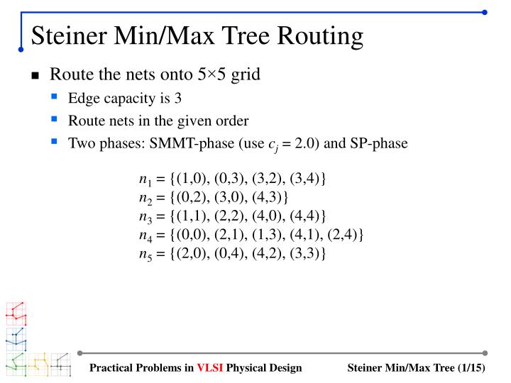
Steiner Min/Max Tree Routing • Route the nets onto 5×5 grid • Edge capacity is 3 • Route nets in the given order • Two phases: SMMT-phase (use cj = 2.0) and SP-phase n1 = {(1,0), (0,3), (3,2), (3,4)} n2 = {(0,2), (3,0), (4,3)} n3 = {(1,1), (2,2), (4,0), (4,4)} n4 = {(0,0), (2,1), (1,3), (4,1), (2,4)} n5 = {(2,0), (0,4), (4,2), (3,3)} Practical Problems in VLSI Physical Design
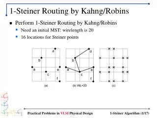
SMMT-Phase • Route first net • Net n1: HPBB = 7, edge weights = 0 (no edge usage yet) • MST is not unique • SMMT: max-weight = 0, wirelength = 9 < 2.0 (= cj) × 7 Practical Problems in VLSI Physical Design
SMMT-Phase • Route second net • Net n2: HPBB = 7, edge weights reflect routing of n1 • SMMT: max-weight = 0, wirelength = 10 < 2.0 × 7 Practical Problems in VLSI Physical Design
SMMT-Phase • Route third net • Net n3: HPBB = 7, edge weights reflect routing of n1 andn2 • SMMT: max-weight = 1, wirelength = 15 > 2.0 × 7 !! • So we reject this SMMT (routing failed) Practical Problems in VLSI Physical Design
SMMT-Phase • Route fourth net • Net n4: HPBB = 8, edge weights reflect routing of n1 andn2 • SMMT: max-weight = 1, wirelength = 15 < 2.0 × 8 Practical Problems in VLSI Physical Design
SMMT-Phase • Route fifth net • Net n5: HPBB = 8, edge weights reflect routing of n1,n2,n4 • SMMT: max-weight = 1, wirelength = 12 < 2.0 × 8 Practical Problems in VLSI Physical Design
Summary of SMMT-Phase Practical Problems in VLSI Physical Design
SP-Phase • Reroute first net • SMMT(n1): wirelength = 9 • Source node s: (3,2) (= arrow), geometric center among terminals • Sinks are added to s in this order: (3,4), (0,3),(1,0) • SP(n1): wirelength = 8 Practical Problems in VLSI Physical Design
SP-Phase • Reroute second net • SMMT(n2): wirelength = 10 • Routing graph reflects rerouting of n1, i.e., SP(n1) • Source node s = (3,0), sinks are added (4,3), (0,2) • SP(n2): wirelength = 7 Practical Problems in VLSI Physical Design
SP-Phase • Reroute third net • SMMT(n3): does not exist due to routing failure • Routing graph reflects rerouting of n1 and n2 • Source node s = (2,2), sinks are added (1,1), (4,0), (4,4) • SP(n3): wirelength = 9 Practical Problems in VLSI Physical Design
SP-Phase • Reroute fourth net • SMMT(n4): wirelength = 15 • Routing graph reflects rerouting of n1, n2, n3 • Source node s = (2,1), sinks are added (4,1), (0,0), (1,3), (2,4) • SP(n4): wirelength = 9 Practical Problems in VLSI Physical Design
SP-Phase • Reroute fifth net • SMMT(n5): wirelength = 12 • Routing graph reflects rerouting of n1, n2, n3, n4 • Source node s = (2,0), sinks are added (4,2), (3,3), (0,4) • SP(n5): wirelength = 9 Practical Problems in VLSI Physical Design
Summary of SP-Phase Practical Problems in VLSI Physical Design
SMMT vs SP • SMMT promotes • Even usage of the edges (= less congestion) • Not a fair comparison since n3 is missing in SMMT • Still SMMT tends to minimize congestion Practical Problems in VLSI Physical Design
SMMT vs SP (cont) • SP promotes • Shorter wirelength, higher weight (= more congestion) • Congestion vs wirelength tradeoff exists Practical Problems in VLSI Physical Design