Download
1 / 15
150 likes | 168 Views
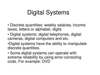
Explore advanced techniques for calibrating digital cameras to achieve optimal image quality. Topics include sensor array technologies, demosaicing methods, and spectral stimulus determinations.

E N D
EE 638: Principles ofDigital Color Imaging Systems Lecture 18: Digital Camera Characterization and Calibration
Image Capture Devices Papers/theses covering these materials can be found in the references under “Capture” • Image Capture Devices: • Scanners • Camera • Camera: • Sensor array technologies • CCD (Charge Coupled Device) • CID (Charge Injection Device) • CMOS (Complementary Metal Oxide Semiconductor) Sensor Array CCD from a HP digital camera
CCD • Phase I Exposure • CMOS & CID Line Registers All detectors have a certain identical sensitivity 1 pixel y address Detector x address
Camera (single chip) • Single chip • CCD • CMOS • CID • Sensor response • Coat cells with three different filter materials How do we get a full resolution array of RGB samples at each pixel? Note that for the blue channel, we want a filter that absorbs the medium and long wavelengths, and transmits the short (blue) wavelengths. Corresponds to trichromatic sensor
Camera (single chip) • Single chip • CCD • CMOS • CID • Sensor response • Coat cells with three different filter materials Demosaic to get full resolution R, G, B Inverse problem Corresponds to trichromatic sensor
Camera (cont.) • Three chips • Foveon sensor R sensor • More expensive, • but do get full resolution • no demosaicing, • do have to worry • about registration G sensor Bean-splitter B sensor incident light • More expensive, • but get full resolution • No registration issues • but have cross-talk • & efficiency issues Layered Chip
Sensor Output • “Linear” proportional to photon count similar to CRT monitor model. • Camera models exist that provide “raw” output. NLR A/D NLG A/D NLB A/D Gamma correction
To determine nonlinearities, have to perform device characterization. • Set-up: illumination Target Target camera This is very similar to process used to determine nonlinearities for a scanner, except that scanner and X-Rite DTP 70 provide their own illumination, which can be more carefully controlled. Colorimeter
To determine nonlinearities NLR, NLG, NLB, need a special facility of stimuli. (Target illuminant) • Let be the spectral stimulus of the i-th patch. • Want • then k— doesn’t depend on i l— doesn’t depend on i
Caveat Full colorant Rc Halftoned Target Kodak Q60 and Macbeth Color Checker targets are not printed, and therefore do not suffer from halftoning issues. paper white Sensor pixels Fraction of patch covered by colorant Fraction of patch not covered by colorant
-1 • Remainder of camera characterization requires finding T: • 1) 2) NLR -1 NLG -1 NLB
Normal approach for finding T is to measure large set of patches & perform linear regression. illumination Target Target camera NL Colorimeter Regression
Summary • 1) Typically can get < accuracy for displays (monitors) because we only need visual independence of primaries. • 2) For capture, have to have sensor response span HVS, i.e. there must exist a 3x3 matrix B such that • No.2 is much more restrictive than No.1 • Above procedure will typically yield ~ (average error = ?)
To do better, could use double exposure where illuminant is charged between exposures, or we place a filter over the lens for the second exposure. • This delves into an area sometimes known as Hi-Fi (High Fidelity) Color or Spectral Color. We will talk about this later in the course. • Another interesting and recently very popular topic related to camera characterization and calibration is high dynamic range (HDR) imaging. We may talk about this later in the semester.