Download
1 / 14
200 likes | 356 Views
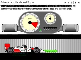
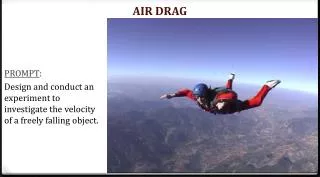
Aerodynamic Drag Force. Air resistance (fluid resistance) motion of the air flowing past projectile equal to projectile’s velocity BUT in the opposite direction of projectile’s motion. Headwind Tailwind. V drag + V headwind flow velocity acting on body body v = 20mps

E N D
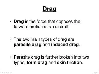
Aerodynamic Drag Force • Air resistance (fluid resistance) • motion of the air flowing past projectile • equal to projectile’s velocity BUT in the opposite direction of projectile’s motion
Headwind Tailwind • Vdrag+ Vheadwind • flow velocity acting on body • body v = 20mps • Vheadwind= 5mps • Vres= ------------- • Vdrag - Vtailwind • flow velocity acting on body • body v = 20mps • Vtailwind= 5mps • Vres= ------------
Skin Friction Profile Drag • most noticed @ low v • rubbing of layers of air adjacent to projectile • with: flow v, surface size, surface roughness • secondary concern • with area exposed to approaching air flow • with projectile v • lead side = pressure • trail side = pressure • main source of Drag
STREAMLINING • Achieved by: 1. decreasing size of area facing oncoming airflow 2. tapering leading side - air is not abruptly moved • Streamlining results in: A. more laminar flow past body with less “wake” B. less turbulence behind bodyless difference in pressure zones between front and tail of body
Mass of Projectile and Drag Effect • a =Fm • a in this case stands for deceleration [negative a] • deceleration =Fm • deceleration inversely proportional to projectile m
Drag Factors FDrag = ½ CD Aρv² • Skin Friction and Profile Drag • CDcoefficient of drag, indicates how streamlined a projectile is (low number = very streamlined) • A is the frontal area of projectile facing the flow • ρ (rho) is the air density(density less in warm air and at higher altitude) • v² means if v doubles, drag quadruples
Profile Drag increases froma to c as more AREA is exposed to oncoming airflow AREAa: ----------b: ----------c: ---------- FIG K.10 pg 424
FLUID LIFT FORCE • FL (Lift Force) always perpendicular to direction of the oncoming air flow • Lift can be upward, downward, lateral • FL due to difference in pressure zones on opposite sides of projectile • Bernoulli’s Principle: • high flow velocity creates ------- pressure zone • low flow velocity creates -------- pressure zone
flow v on top p zone on top p zone on bottom upward Flift flow v on top p zone on top p zone on bottom downward Flift
8-May-2001National Post from“New Scientist”David Anderson disputesDaniel Bernouilli’s Principle
LIFT : DRAG • Maximize LIFT FORCE by creating an optimal angle of attack or shaping projectile like an airfoil • Minimize DRAG FORCE with a moderate ATTACK • FL = ½ CL Aρv²CL (lift coefficient) A (area of pressure)ρ(air density) v² (air flow velocity)
FIG K.9 page 424
http://www.grc.nasa.gov/WWW/K-12/airplane/incline.html LIFT and DRAG: Effects of Inclination of an AIRFOIL