Download

1 / 64
730 likes | 1.42k Views
CS147. Lecture 3. Boolean Algebra, Logic Gates. 2x. Prof. Sin-Min Lee Department of Computer Science. Chapter Goals. Boolean Algebra Identify the basic gates and describe the behavior of each Combine basic gates into circuits

E N D
CS147 Lecture 3. Boolean Algebra, Logic Gates 2x Prof. Sin-Min Lee Department of Computer Science
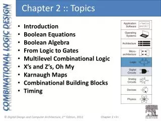
Chapter Goals • Boolean Algebra • Identify the basic gates and describe the behavior of each • Combine basic gates into circuits • Describe the behavior of a gate or circuit using Boolean expressions, truth tables, and logic diagrams
What is a gate? • Combination of transistors that perform • binary logic • So called because one logic state enables • or “gates” another logic state • For each gate, the symbol, the truth table, • and the formula are shown
<B; +, *,’, 0,1> Algebraic System Binary operations: +,* Unary operation: ‘
jasonm: Redo table (p101) Properties of Boolean Algebra Page 101
Computers • There are three different, but equally powerful, notational methods for describing the behavior of gates and circuits • Boolean expressions • logic diagrams • truth tables
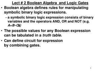
Boolean algebra • Boolean algebra: expressions in this algebraic notation are an elegant and powerful way to demonstrate the activity of electrical circuits
Truth Table • Logic diagram: a graphical representation of a circuit • Each type of gate is represented by a specific graphical symbol • Truth table: defines the function of a gate by listing all possible input combinations that the gate could encounter, and the corresponding output
Gates • Let’s examine the processing of the following six types of gates • NOT • AND • OR • XOR • NAND • NOR
NOT Gate • A NOT gate accepts one input value and produces one output value Figure 4.1 Various representations of a NOT gate
NOT Gate • By definition, if the input value for a NOT gate is 0, the output value is 1, and if the input value is 1, the output is 0 • A NOT gate is sometimes referred to as an inverter because it inverts the input value
AND Gate • An AND gate accepts two input signals • If the two input values for an AND gate are both 1, the output is 1; otherwise, the output is 0 Figure 4.2 Various representations of an AND gate
OR Gate • If the two input values are both 0, the output value is 0; otherwise, the output is 1 Figure 4.3 Various representations of a OR gate
XOR Gate • XOR, or exclusive OR, gate • An XOR gate produces 0 if its two inputs are the same, and a 1 otherwise • Note the difference between the XOR gate and the OR gate; they differ only in one input situation • When both input signals are 1, the OR gate produces a 1 and the XOR produces a 0
XOR Gate Figure 4.4 Various representations of an XOR gate
NAND and NOR Gates • The NAND and NOR gates are essentially the opposite of the AND and OR gates, respectively Figure 4.5 Various representations of a NAND gate Figure 4.6 Various representations of a NOR gate
Gates with More Inputs • Gates can be designed to accept three or more input values • A three-input AND gate, for example, produces an output of 1 only if all input values are 1 Figure 4.7 Various representations of a three-input AND gate
3-Input And gate A B C Y 0 0 0 0 0 0 1 0 0 1 0 0 0 1 1 0 1 0 0 0 1 0 1 0 1 1 0 0 1 1 1 1 Y = A . B . C
Constructing Gates • A transistor is a device that acts, depending on the voltage level of an input signal, either as a wire that conducts electricity or as a resistor that blocks the flow of electricity • A transistor has no moving parts, yet acts like a switch • It is made of a semiconductor material, which is neither a particularly good conductor of electricity, such as copper, nor a particularly good insulator, such as rubber
Circuits • Two general categories • In a combinational circuit, the input values explicitly determine the output • In a sequential circuit, the output is a function of the input values as well as the existing state of the circuit • As with gates, we can describe the operations of entire circuits using three notations • Boolean expressions • logic diagrams • truth tables
Combinational Circuits • Gates are combined into circuits by using the output of one gate as the input for another AND OR AND Page 99
jasonm: Redo to get white space around table (p100) Combinational Circuits • Because there are three inputs to this circuit, eight rows are required to describe all possible input combinations • This same circuit using Boolean algebra: (AB + AC) Page 100
jasonm: Redo table to get white space (p101) Now let’s go the other way; let’s take a Boolean expression and draw • Consider the following Boolean expression: A(B + C) Page 100 Page 101 • Now compare the final result column in this truth table to the truth table for the previous example • They are identical
Simple design problem • A calculation has been done and its results • are stored in a 3-bit number • Check that the result is negative by anding • the result with the binary mask 100 • Hint: a “mask” is a value that is anded with • a value and leaves only the important bit
Now let’s go the other way; let’s take a Boolean expression and draw • We have therefore just demonstrated circuit equivalence • That is, both circuits produce the exact same output for each input value combination • Boolean algebra allows us to apply provable mathematical principles to help us design logical circuits
Adders • At the digital logic level, addition is performed in binary • Addition operations are carried out by special circuits called, appropriately, adders
Adders • The result of adding two binary digits could produce a carry value • Recall that 1 + 1 = 10 in base two • A circuit that computes the sum of two bits and produces the correct carry bit is called a half adder • Notice the Sum & Carry are NEVER both 1. (XOR) (AND)
Adders • Circuit diagram representing a half adder • Two Boolean expressions: sum = A B carry = AB Page 103
Adders • A circuit called a full adder takes the carry-in value into account Figure 4.10 A full adder
Adding Many Bits • To add 2 8-bit values, we can duplicate a full-adder circuit 8 times. The carry-out from one place value is used as the carry in for the next place value. The value of the carry-in for the rightmost position is assumed to be zero, and the carry-out of the leftmost bit position is discarded (potentially creating an overflow error).
B A Q C Universal Gates How to use NOR gate to build a NOT gate? Truth Table Logic Gates Hint! Link inputs B & C together (to a same source). When A = 0, B = C = A = 0 When A = 1, B = C = A = 1