Download
1 / 26
290 likes | 350 Views
This informative presentation by Dr. Balasani Srinivasa Rao discusses the construction, speed of rotation, and internal voltage of synchronous generators. Learn about the equivalent circuit, phasor diagrams, power, and measuring parameters. Explore the various components such as rotor windings, slip rings, brushes, and the advantages of brushless exciters. Discover how synchronous generators convert mechanical energy into AC electric energy for power plants. Improve your knowledge of the steady-state operation and construction details of these essential machines.

E N D
ENERGY CONVERSION SYNCHRONOUS GENERATORS Presented by Dr. BALASANI SRINIVASA RAO, Professor DEPARTMENT OF ELECTRICAL AND ELECTRONICS ENGINEERING VISAKHA INSTITUTE OF ENGINEERING & TECHNOLOGY
SYNCHRONOUS GENERATORSSummary 1. Synchronous Generator Construction 2. Speed of Rotation of a Synchronous Generator 3. Internal Voltage of a Synchronous Generator 4. Equivalent Circuit of a Synchronous Generator 5. Phasor Diagram of a Synchronous Generator Eq. cct. 6. Power and Torque in Synchronous Generator • Measuring Synchronous Generator Model Parameters
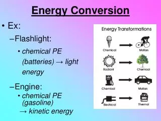
SYNCHRONOUS GENERATOR CONSTRUCTION • SYN. GEN. USED to CONVERT MECHANICAL ENERGY TO AC ELECTRIC ENERGY: GENERATORS IN POWER PLANTS • STEADY STATE OPERATION of SYNCHRONOUS GENERATORS DISCUSSED HERE • GENERATOR CONSTRUCTION - in synchronous generator, rotor winding energized by dc source to develop rotor magnetic field - rotor is turned by a prime mover, producing a rotating magnetic field which induce 3 phase voltages in stator windings In general rotor carry the “field windings” , while “armaturewindings”(or “stator windings”) carry the main voltages of machine • therefore: • rotor windings ≡ field windings • stator windings ≡ armature windings
SYNCHRONOUS GENERATOR CONSTRUCTION • Rotor of synchronous machine can be Nonsalient:2 pole rotorSalient:six-pole rotor
SYNCHRONOUS GENERATOR CONSTRUCTION • Photograph of a salient 8-pole synchronous machine rotor
SYNCHRONOUS GENERATOR CONSTRUCTION • Rotorexperience varying magnetic fields,therefore is constructedof thin laminations to reduce eddy current losses • To supply the rotor winding while it is rotating, special arrangement employed to connect its terminal to dc supply 1. supply dc power from an external dc source to rotor by means ofslip rings 2. supply dc power from a special dc power sourcemounted on shaft of rotor
SYNCHRONOUS GENERATOR CONSTRUCTION • SLIP RINGS: are metal ringsencircling shaft and are insulated from it - one end of rotor winding is connected to each of the 2 slip rings - and a stationary brush mounted on the machine casing ride on each slip ring • Brush:a block of graphite like carbon compound that conducts and has low friction • same dc voltage is applied to field winding during rotation
SYNCHRONOUS GENERATOR CONSTRUCTION • Problems associated with slip rings and brushes: 1- increase the required maintenance(brushes should be examined for wear regularly) 2- brush voltage drop results in significant power losses if field current is high • Despite of above problems,SLIP RINGS & BRUSHESused for smallersynchronous machines since is cost-effective
SYNCHRONOUS GENERATOR CONSTRUCTION • on larger generator & motors, brushless exciters are used • Brushless Exciter:is a smaller ac generatorwith its field circuit mounted on stator & its armature circuit mounted on rotor shaft - 3 phase output of exciter generator rectified by a 3 phase rectifier mounted also on shaft • By controlling small dc field current of exciter generator, it is possible to fed (and also adjust) field current of main machine without slip rings and brushes
SYNCHRONOUS GENERATOR CONSTRUCTION • Schematic arrangement of a brushless exciter
SYNCHRONOUS GENERATOR CONSTRUCTION • Photograph of a synchronous machine with brushless exciter
SYNCHRONOUS GENERATOR CONSTRUCTION • a small pilot exciter often included in system to have the excitation of generator independent of any external power sources • A pilot exciteris a small ac generator with permanent magnets mounted on rotor shaft & a 3 phase winding on stator • It produces power for field circuit of exciter, which in turn controls the field circuit of main machine • With pilot exciteron shaft of generator, no external electric power is required to run generator • Many Syn. Gen.s with brushless exciters also have slip rings and brushes, as an auxiliary source of dc field in emergencies
SYNCHRONOUS GENERATOR CONSTRUCTION • Brushless exciter including a pilot exciter
SYNCHRONOUS GENERATOR Speed of rotation of synchronous generator • synchronous generators are synchronous, during their operation means: electrical frequency is synchronized with mechanical speed of rotor • Relation between electrical frequency of stator and mechanical speed of rotor as shown before: fe=nm p / 120 fe : electrical frequency in Hz nm: speed of rotor in r/min p: number of poles
SYNCHRONOUS GENERATOR Speed of rotation of synchronous generator • Electric power generated at 50 or 60 Hz, so rotor must turn at fixed speed depending on number of poles on machine • To generate 60 Hz in 2 pole machine, rotor must turn at 3600 r/min, and to generate 50 Hz in 4 pole machine, rotor must turn at 1500 r/min • INTERNAL GENERATED VOLTAGE OF A SYNCHRONOUS GENERATOR • magnitude of induced voltage in one phasedetermined in last section:EA=√2 π NCφ f
SYNCHRONOUS GENERATORINTERNAL GENERATED VOLTAGE • Induced voltage depends on flux φ, frequency or speed of rotation f, & machine’s construction • Last equation can be rewritten as: EA=K φω K=NC/√2 (if ω= ωe) K=NC p/√2 (if ω= ωm) • Note: EA proportional to flux & speed, while flux depend on current in rotor winding IF , therefore EA is related to IF& its plot named: magnetization curve, or O/C characteristic
SYNCHRONOUS GENERATORINTERNAL GENERATED VOLTAGE • Plots of flux vs IF and magnetization curve
SYNCHRONOUS GENERATOREQUIVALENT CIRCUIT • To develop a relation for Vφas terminal voltage of generator which is different from internal voltage EA equivalent circuit is needed • Reasons for Vφto be different from EA 1- distortion of air-gap magnetic field magnetic field due to current flowing in stator, calledarmature reaction 2- self-inductance of armature coils 3- resistance of armature coils 4- effect of salient-pole rotor shapes (ignored as machines have cylindrical rotors)
SYNCHRONOUS GENERATOREQ. CCT. (ARM. REAC)… • Last figure shows a 2 pole rotor spinning inside a 3 phase stator, without load • Rotor magnetic field BR develop a voltage EA as discussed in last chapter voltage is positive out of conductors, at top, and negative into the conductors at bottom of figure • When there is no load on generator, armature current zero, EA=Vφ • If generator be connected to a lagging load, peak current occur at an angle behind peak voltage as in fig (b)
SYNCHRONOUS GENERATOREQ. CCT. (ARM. REAC)… • Current flowing in stator windings produces its magnetic field • Stator magnetic field named BS & its direction found by R.H.R. as shown in fig(c) this BS produces another voltage in stator, named Estat and shown in figure • Having these 2 voltage components in stator windings, total voltage in one phase is sum of EA and Estat : Vφ=EA+Estat and Bnet=BR+BS angle of Bnet coincide with angle of Vφshown in fig (d)
SYNCHRONOUS GENERATOREQ. CCT. (ARM. REAC)… • To model effect of armature reaction, note: 1- Estat lies at an angle of 90◦ behind plane of maximum current IA 2- Estat directly proportional to IA and X is constant of proportionality • Estat= -j X IA • voltage in one phase Vφ= EA-j X IA • Following eq. cct. can be developed
SYNCHRONOUS GENERATOREQ. CCT. (ARM. REAC)… • Armature reaction voltagecan be modeled as an inductor in series with internal induced voltage • In addition to armature reaction, stator coils have a self-inductance and a resistance • stator self-inductance named LA (its reactance XA) and stator resistance is RA : Vφ=EA- jXIA- jXAIA- RAIA • Armature reaction & self-inductance in machine both represented by reactance, normally they are combined to a single reactance as : XS=X+XA Vφ=EA- jXS IA- RAIA
SYNCHRONOUS GENERATOREQ. CCT. (ARM. REAC)… • equivalent circuit of a 3 phase synchronous generator can be shown as follows:
SYNCHRONOUS GENERATOREQ. CCT. … • Figure shows a dc source, supplying rotor winding, modeled by coil inductance & resistance in series with an adjustable resistor Radj that controls current • Rest of equivalent circuit consists of model for each phase • the voltages and currents of each phase are 120◦ apart with same magnitude • Three phases can be connected in Y or Δ • If connected in Y : VT=√3 Vφ • If connected in Δ: VT= Vφ
SYNCHRONOUS GENERATOREQ. CCT… • The per phase equivalent circuit is shown below • can be employed when loads of 3 phase are balanced