Download
1 / 11
110 likes | 228 Views
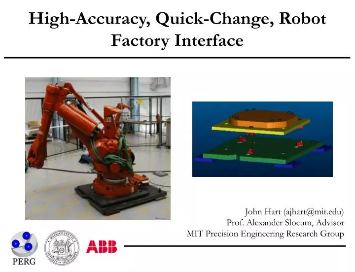
High-Accuracy, Quick-Change, Robot Factory Interface. John Hart (ajhart@mit.edu) Prof. Alexander Slocum, Advisor MIT Precision Engineering Research Group. Project Goals. Design, test, and demonstrate production feasibility of a modular robot baseplate with kinematic couplings as locators:.

E N D
High-Accuracy, Quick-Change, Robot Factory Interface John Hart (ajhart@mit.edu)Prof. Alexander Slocum, AdvisorMIT Precision Engineering Research Group
Project Goals Design, test, and demonstrate production feasibility of a modular robot baseplate with kinematic couplings as locators: • A repeatable, rapidly exchangeable interface between the foot (three balls/contactors) and floor plate (three grooves/targets) • Calibrate robots at ABB to a master baseplate • Install production baseplates at the customer site and calibrated the kinematic couplings directly to in-cell tooling • Install robot according to refined mounting process with gradual, patterned preload to mounting bolts • TCP-to-tooling relationship is a deterministic frame transformation • Base calibration data handling is merged with ABB software, enabling 0.1 mm TCP error contribution from repeatability and exchangeability error of kinematic couplings
Prototype Coupling Designs Design 3-point kinematic coupling mounts for the 6400R foot: Canoe Ball • Six “point” contacts • 0.5m radius ball surface • 20 mm diameter elastic Hertzian contact Three-Pin • Three line + three surface contacts • In-plane preload overcomes friction to deterministically seat pins • Vertical bolt preload engages horizontal contact surfaces
Prototype Coupling Designs Groove/Cylinder • Twelve line contacts • Aluminum cylinders • Apply bolt preload (elastic deflection of cylinders) for dynamic stability
Prototype Base Mounting Tests at ABB Robotics Vasteras, July/August 2001: • Static (bolted) and dynamic (5-point path) repeatability of canoe ball and three-pin interfaces • Static (manipulator rest only) repeatability of groove/cylinder interface • Test both basic (air wrench) and refined (torque wrench, greased bolts) mounting processes • Measure tool point motion using Leica LTD500 Laser Tracker • Repeatability of robot path + measurement system approximately 20 microns
Repeatability Performance • Canoe balls vs. BMW base = 83% reduction • Three-pin vs. BMW base = 85% reduction • Cylinders vs. BMW base = 92% reduction • Refined mounting vs. basic mounting = 50-70% reduction • 8-bolt blue pallet repeatability (not shown) = 1.63 mm
Interchangeability Error Model Consider stackup of errors in coupling manufacturing, mounting plate manufacturing, and coupling-to-plate assembly: For example in z-direction of a ball mount, tolerances: • Sphere radius = dRsph • Contact point to bottom plane = dhR • Measurement feature height = dhmeas • Protrusion height = dhprot Each dimension is perturbed by generating a random variate, e.g. for mounting hole placement:
Interchangeability Solution Method Linear system of 24 constraint equations between the balls and grooves – accounts for both positional and angular misalignment: Contact sphere centers must be at minimum (normal) distance between the groove flats, e.g.: By geometry, the combined error motion of contact spheres is known with respect to the error motion of their mounting plate. For small angles, e.g.: Solve linear system and place six error parameters in HTM: q1, b1 = initial, final center positions; N1 = groove normal; R1 = sphere radius. (qS,1, qS,1, qS,1) = initial center positions; (xS,1, yS,1, zS,1) = final center positions.
Interchangeability Results Simulate interchangeablity error from manufacturing variation: • Calibrate interfaces by measuring contacts and calculating interface error transformation • Model direct measurement of pins + contacts, and offset measurement of canoe balls • Exchangeability is error between calculated and true interface transformation, given chosen level of calibration and manufacturing tolerances (low, med, high) • 250-trial Monte Carlo simulation in MATLAB at each calibration level Three-pin interchangeability: 0 = no interface calibration 3 = full (x,y,z) of pins and contact surfaces
Total Mechanical Accuracy “Quick-Change” Accuracy = Repeatability + Exchangeability (measured) (simulated) Canoe balls Three-pin Groove/cylinder 0.22 mm = 0.06 + 0.16* 0.12 mm = 0.07 + 0.05 - = 0.06** + (Incomplete) • Interface calibration decouples accuracy from manufacturing tolerances of mounting plates and couplings (if direct measurement of contacts) • Results show repeatability is highly f(mounting process) – this may present a performance limit for factory mountings; interface should be micron-repeatable under perfect conditions • Totally, a near-deterministic prediction of robot interface accuracy *driven by error of offset position measurement **static only
Recommended Next Steps • Test groove/cylinder interface with preload + motion • Test traditional quasi-kinematic couplings • Evaluate long-term dynamic performance • Production three-pin adaptation to BMW base • Canoe ball 4-point mounting for Voyager? • Build kinematic coupling “Expert System” – combine test results, simulation results, etc. into design tool that gives minimum cost recommendation as f(accuracy requirement)