Download

1 / 53
530 likes | 563 Views
Learn how to model complex systems using hierarchical and object-oriented approaches, with a focus on symbol-instance tables, graphs, trees, articulated models, and transformation matrices. Explore examples like car and robot arm models, including code for OpenGL implementation.

E N D
Hierarchical and Object-Oriented Modeling Dr. Giorgos A. Demetriou Dr. Stephania Loizidou Himona Computer Science Frederick Institute of Technology
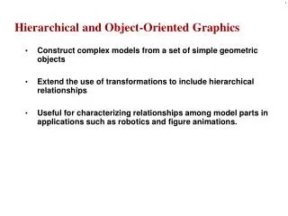
Instance Transformation • Start with a prototype object (a symbol) • Each appearance of the object in the model is an instance • Must scale, orient, position • Defines instance transformation
Symbol-Instance Table • Can store a model by assigning a number to each symbol and storing the parameters for the instance transformation
Relationships in Car Model • Symbol-instance table does not show relationships between parts of model • Consider model of car • Chassis + 4 identical wheels • Two symbols • Rate of forward motion determined by rotational speed of wheels
Structure Through Function Calls car(speed) { chassis() wheel(right_front); wheel(left_front); wheel(right_rear); wheel(left_rear); } • Fails to showrelationships well • Look at problem using a graph
Graphs • Set of nodes and edges (links) • Edge connects a pair of nodes • Directed or undirected • Cycle: directed path that is a loop loop
Tree • Graph in which each node (except the root) has exactly one parent node • May have multiple children • Leaf or terminal node: no children root node leaf node
DAG Model • If we use the fact that all the wheels are identical, we get a directed acyclic graph • Not much different than dealing with a tree
Modeling with Trees • Must decide what information to place in nodes and what to put in edges • Nodes • What to draw • Pointers to children • Edges • May have information on incremental changes to transformation matrices (can also store in nodes)
Robot Arm parts in their own coodinate systems robot arm
Articulated Models • Robot arm is an example of an articulated model • Parts connected at joints • Can specify state of model by giving all joint angles
Relationships in Robot Arm • Base rotates independently • Single angle determines position • Lower arm attached to base • Its position depends on rotation of base • Must also translate relative to base and rotate about connecting joint • Upper arm attached to lower arm • Its position depends on both base and lower arm • Must translate relative to lower arm and rotate about joint connecting to lower arm
Required Matrices • Rotation of base: Rb • Apply M = Rb to base • Translate lower arm relative to base: Tlu • Rotate lower arm around joint: Rlu • Apply M = Rb Tlu Rlu to lower arm • Translate upper arm relative to upper arm: Tuu • Rotate upper arm around joint: Ruu • Apply M = Rb Tlu Rlu Tuu Ruu to upper arm
OpenGL Code for Robot robot_arm() { glRotate(theta, 0.0, 1.0, 0.0); base(); glTranslate(0.0, h1, 0.0); glRotate(phi, 0.0, 1.0, 0.0); lower_arm(); glTranslate(0.0, h2, 0.0); glRotate(psi, 0.0, 1.0, 0.0); upper_arm(); }
Tree Model of Robot • Note code shows relationships between parts of model • Can change “look” of parts easily without altering relationships • Simple example of tree model • Want a general node structure for nodes
Possible Node Structure Code for drawing part or pointer to drawing function linked list of pointers to children matrix relating node to parent
Generalizations • Need to deal with multiple children • How do we represent a more general tree? • How do we traverse such a data structure? • Animation • How to use dynamically? • Can we create and delete nodes during execution?
Building the Model • Can build a simple implementation using quadrics: ellipsoids and cylinders • Access parts through functions • torso() • left_upper_arm() • Matrices describe position of node with respect to its parent • Mlla positions left lower leg with respect to left upper arm
Display and Traversal • The position of the figure is determined by 11 joint angles (two for the head and one for each other part) • Display of the tree requires a graph traversal • Visit each node once • Display function at each node that describes the part associated with the node, applying the correct transformation matrix for position and orientation
Transformation Matrices • There are 10 relevant matrices • M positions and orients entire figure through the torso which is the root node • Mh positions head with respect to torso • Mlua, Mrua, Mlul, Mrul position arms and legs with respect to torso • Mlla, Mrla, Mlll, Mrll position lower parts of limbs with respect to corresponding upper limbs
Stack-based Traversal • Set model-view matrix to M and draw torso • Set model-view matrix to MMh and draw head • For left-upper arm need MMlua and so on • Rather than recomputing MMlua from scratch or using an inverse matrix, we can use the matrix stack to store M and other matrices as we traverse the tree
Traversal Code figure() { glPushMatrix() torso(); glRotate3f(…); head(); glPopMatrix(); glPushMatrix(); glTranslate3f(…); glRotate3f(…); left_upper_arm(); glPopMatrix(); glPushMatrix(); save present model-view matrix update model-view matrix for head recover original model-view matrix save it again update model-view matrix for left upper arm recover and save original model-view matrix again rest of code
Analysis • The code describes a particular tree and a particular traversal strategy • Can we develop a more general approach? • Note that the sample code does not include state changes, such as changes to colors • May also want to use glPushAttrib and glPopAttrib to protect against unexpected state changes affecting later parts of the code
General Tree Data Structure • Need a data structure to represent tree and an algorithm to traverse the tree • We will use a left-child right sibling structure • Uses linked lists • Each node in data structure is two pointers • Left: next node • Right: linked list of children
Tree node Structure • At each node we need to store • Pointer to sibling • Pointer to child • Pointer to a function that draws the object represented by the node • Homogeneous coordinate matrix to multiply on the right of the current model-view matrix • Represents changes going from parent to node • In OpenGL this matrix is a 1D array storing matrix by columns
C Definition of treenode typedef struct treenode { Glfloat m[16]; void (*f)(); struct treenode *sibling; struct treenode *child; } treenode;
Defining the torso node treenode torso_node, head_node, lua_node, … ; /* use OpenGL functions to form matrix */ glLoadIdentity(); glRotatef(theta[0], 0.0, 1.0, 0.0); /* move model-view matrix to m */ glGetFloatv(GL_MODELVIEW_MATRIX, torso_node.m) torso_node.f = torso; /* torso() draws torso */ Torso_node.sibling = NULL; Torso_node.child = &head_node;
Notes • The position of figure is determined by 11 joint angles stored intheta[11] • Animate by changing the angles and redisplaying • We form the required matrices usingglRotateandglTranslate • More efficient than software • Because the matrix is formed in model-view matrix, we may want to first push original model-view matrix on matrix stach
Preorder Traversal void traverse(treenode *root) { if(root == NULL) return; glPushMatrix(); glMultMatrix(root->m); root->f(); if(root->child != NULL) traverse(root->child); glPopMatrix(); if(root->sibling != NULL) traverse(root->sibling); }
Notes • We must save modelview matrix before multiplying it by node matrix • Updated matrix applies to children of node but not to siblings which contain their own matrices • The traversal program applies to any left-child right-sibling tree • The particular tree is encoded in the definition of the individual nodes • The order of traversal matters because of possible state changes in the functions
Dynamic Trees • If we use pointers, the structure can be dynamic typedef treenode *tree_ptr; tree_ptr torso_ptr; torso_ptr = malloc(sizeof(treenode)); • Definition of nodes and traversal are essentially the same as before but we can add and delete nodes during execution
Limitations of Immediate Mode Graphics • When we define a geometric object in an application, upon execution of the code the object is passed through the pipeline • It then disappears from the graphical system • To redraw the object, either changed or the same, we must reexecute the code • Display lists provide only a partial solution to this problem
OpenGL and Objects • OpenGL lacks an object orientation • Consider, for example, a green sphere • We can model the sphere with polygons or use OpenGL quadrics • Its color is determined by the OpenGL state and is not a property of the object • Defies our notion of a physical object • We can try to build better objects in code using object-oriented languages/techniques
cube data glRotate Application results Imperative Programming Model • Example: rotate a cube • The rotation function must know how the cube is represented • Vertex list • Edge list
Application Cube Object message Object-Oriented Programming Model • In this model, the representation is stored with the object • The application sends a message to the object • The object contains functions (methods) which allow it to transform itself
C/C++ • Can try to use C structs to build objects • C++ provides better support • Use class construct • Can hide implementation using public, private, and protected members in a class • Can also use friend designation to allow classes to access each other
Cube Object • Suppose that we want to create a simple cube object that we can scale, orient, position and set its color directly through code such as cube mycube; mycube.color[0]=1.0; mycube.color[1]=mycube.color[2]=0.0; mycube.matrix[0][0]=………
Cube Object Functions • We would also like to have functions that act on the cube such as • mycube.translate(1.0, 0.0,0.0); • mycube.rotate(theta, 1.0, 0.0, 0.0); • setcolor(mycube, 1.0, 0.0, 0.0); • We also need a way of displaying the cube • mycube.render();
Building the Cube Object class cube { public: float color[3]; float matrix[4][4]; // public methods private: // implementation }
The Implementation • Can use any implementation in the private part such as a vertex list • The private part has access to public members and the implementation of class methods can use any implementation without making it visible • Render method is tricky but it will invoke the standard OpenGL drawing functions such as glVertex
Other Objects • Other objects have geometric aspects • Cameras • Light sources • But we should be able to have nongeometric objects too • Materials • Colors • Transformations (matrices)
Application Code cube mycube; material plastic; mycube.setMaterial(plastic); camera frontView; frontView.position(x ,y, z);
Light Object class light { // match Phong model public: boolean type; //ortho or perspective boolean near; float position[3]; float orientation[3]; float specular[3]; float diffuse[3]; float ambient[3]; }
Scene Descriptions • If we recall figure model, we saw that • We could describe model either by tree or by equivalent code • We could write a generic traversal to display • If we can represent all the elements of a scene (cameras, lights,materials, geometry) as C++ objects, we should be able to show them in a tree • Render scene by traversing this tree
Preorder Traversal glPushAttrib glPushMatrix glColor glTranslate glRotate Object1 glTranslate Object2 glPopMatrix glPopAttrib …