Download
1 / 28
1.02k likes | 2.64k Views
Introduction to pic microcontroller. Pic 18 series. Criteria for choosing a microcontroller. Speed: what is the highest speed that the microcontroller supports. Packaging: 40pin DIP(dual inline package) or QFP (quad flat package) etc. Power consumption: Size of RAM & ROM on chip.

E N D
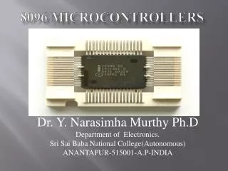
Introduction to pic microcontroller Pic 18 series
Criteria for choosing a microcontroller Speed: what is the highest speed that the microcontroller supports. Packaging: 40pin DIP(dual inline package) or QFP (quad flat package) etc. Power consumption: Size of RAM & ROM on chip. The # of I/O pins & timers on chip.
ARCHITECTURE & ASM LANGUAGE PROGARMING • WREG register • MOVLW instruction • MOVLW 25H :move value 25H into WREG • ADDLW instruction • MOVLW 25H :move value 25H into WREG • ADDLW 34H :add value 34 to WREG :VALUE(W=W(VALUE)+34H) • PIC FILE REGISTERS • SFRS(SPECIAL FUNCTION REGISTERS) • GPRS(GENERAL PURPOSE REGISTERS) • PIC18F452 1792BYTES=(SFR(256)+GPR(1536))
SFRs (special function registers) Dedicated to special functions such as ALU status , timers, serial communication , I/O ports etc. MOVWF MOVLW 7H MOVWF PORTB :COPY WREG VALUE TO PORT B ADDWF ADDWF FILEREGISTER , D MOVLW 54H MOVWF 45H ADDWF 45H,0 :ADD W AND LOCATION 45H ,STORES RESULT IN WREG
FILE REGISTER INSTRUCTION USING FILEREG OR WREG AS DESTINATION
Addressing modes Cpu can access data in various ways. the data could be in register, or in memory or immediate value.these various ways of accessing data are called addressing modes. The PIC18 provides four distinct addressing modes. Immediate Direct Register indirect Indexed-ROM
Immediate addressing mode Operand is a literal constant Operand comes immediately after opcode. Notice that immediate data is called ‘literal’ in the PIC. It can be used to load information into WREG and selected reg but not in file reg. It can also be used for arithmetic and logic instructions. For example. MOVLW 0X25 ;load 25H to WREG SUBLW D’62’ ;subtract WREG from 62 ANDLW B’01000000’ ;AND WREG with 40H We can use EQU directive also as COUNT EQU 0X30 ………… …… ….. MOVLW COUNT ; WREG=30H
DIRECT ADDRESSING MODE In indirect addressing mode, the operand data is in RAM memory location whose address is known, and this address is given as a part of instruction. In immediate mode letter L in the instruction signifies immediate value. In direct letter F in the instruction signifies address of file reg location. Example MOVLW 0X56 ;WREG =56H(immediate) MOVWF 0X40 ; copy WREG into file reg location 40H MOVFF 0X40,0X50 ;copy data from 40H to 50H Address field is an 8-bit address and can take values from 00-FFh. NOTE: file reg data RAM does not support immediate addressing mode.
Register indirect addressing mode In reg indirect addressing mode, a reg is used as pointer to data RAM location. In PIC18 three registers are used for this purpose FSR0, FSR1,FSR2. (FSR stands for file select reg) FSR is a 12-bit reg allowing access to entire 4096 bytes of data RAM space. We use LFSR to load the RAM address. LSFR 0, 0X30 ; load FSR0 with 30 LSFR 1, 0X40 ; load FSR1 with 40 LSFR 2, 0X6f ; load FSR2 with 6f We use FSR 12-bit reg as piece of 8-bit.(FSRxL,FSRxH(4-bit each high 4 bits are not used)) Indexed-ROM missing.
Programming timers 0 and 1 Every timer needs a clock pulse to tick. Clock source can be internal or external. If we use internal then 1/4th of the frequency of crystal oscillator OSC1, OSC2 is fed into timer. BASIC REGISTERS : Pic18 has an 8-bit architecture so each 16-bit timer is accessed as two separate registers. TMRxL , TMRxR . Each timer has a TCON register. TMR0IF flag bit: TMR0IF bit (timer0 interrupt flag) is a part of the INTCON (interrupt control reg). When timer reaches its max value FFFFh it rolls over to 0000h and TMR0IF is set to 1.
INTCON TMR0IF D2 timer0 interrupt overflow o = timer did not overflow 1 = overflow (FFFF to 0000 or FF to 00 in 8 bit mode) Importance : In 16 bit mode overflows from FFFF to 0000 this flag is raised. In 8 bit it is raised when goes from FF to 00.
16 bit timer programming 16 bit timer allows values 0000 to FFFF.(TMR0H:TMR0L) After loading values timer is started as “ BSF TCON,TMR0ON”. Now monitor timer flag. In order to repeat values are reloaded again and interrupt flag is reset to 0 for next round. Program: create a square wave of 50% duty cycle; BCF TRISB,5 ;pb5 as an output MOVLW 0x08 ;timer0 16 bit no prescaler MOVWF TOCON ;load tcon reg HERE MOVLW 0xFF ;TMR0H= FFh, high byte MOVWF TMR0H ;load TMR0H high byte MOVLW 0xF2 ;TMR0l= F2h, low byte MOVWF TMR0L ;load TMR0H high byte BCF INTCON, TMR0IF ;clear interrupt flag bit BTG PORTB, 5 ;toggle BSF TCON, TMR0ON ;start timer AGAIN BTFSS INTCON, TMR0IF ; monitor timer0 flag until it rolls over BRA AGAIN BCF TOCON, TMR0ON ;stop timer BRA HERE ;load TH,TL again
Finding values to be loaded in timer Assuming XTAL= 10MHz Divide the desired time delay by 0.4 micro sec =n. perform 65536-n. Convert result into hex And load TMR0H,TMR0L